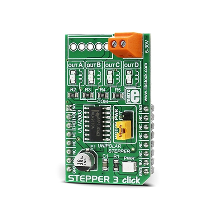
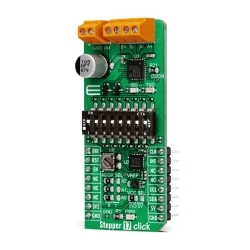
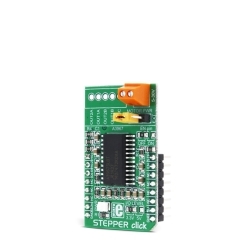
MIKROE Stepper 3 Click
Stepper 3 Click is designed to drive unipolar stepper motors, with a supply voltage applied to the common wire.
Product Overview
Stepper 3 Click is designed to drive unipolar stepper motors, with a supply voltage applied to the common wire. The current flows through the common wire and the motor coil, via the activated current sink driver, to the ground. This Click board™ uses the ULN2003A, a high voltage and current Darlington transistors array IC, as the sink driver. This IC is an ideal solution for this purpose, as it has seven high power Darlington output stages, activated by TTL/CMOS logic level signals, applied to the control pins. This allows driving unipolar stepper motors with up to 30V and 500mA per coil.
The ULN2003A itself is an ideal option for driving inductive loads such as the motor coils, as every channel is equipped with the common cathode clamp diode, which protects the IC from back EMF, typically observed at inductors and coils. Each of its inputs has a 2.7kΩ resistor, making it suitable to be driven by the TTL signal levels. Besides driving unipolar stepper motor as the primary function, this Click board™ can also be used for driving relays, brushed DC motors, or to be used as the logic buffer for a wide range of applications. By combining more than one driver, it is possible to sink more than 500mA.
Stepper 3 Click uses the ULN2003A, a high voltage and current Darlington transistors array IC, from Texas Instruments. This IC is an integrated high power current sink driver with 7 channels, driven by the TTL/CMOS signal levels, typically found on MCUs. This allows implementation of the unipolar stepper motor driver, with up to 30V and 500mA per coil. Motor step progression is performed by alternating the active driver, which sinks the current through the coil connected to the respective driver. The alteration cycle is performed by the MCU, which controls the driver inputs: a HIGH logic level on the input pin will set the corresponding driver to a LOW logic level - it will allow it to sink current.
Switching the power through the coil results in the appearance of the back EMF. This is a generated voltage that opposes the change of the current direction through the inductive load and without proper measures, it can affect the electrical components on the output. For this reason, every driver stage is equipped with the clamping diode, which allows the current generated by the back EMF, to be returned back to the power supply. This effectively protects the Darlingtons on the output stages from inverse voltage polarity.
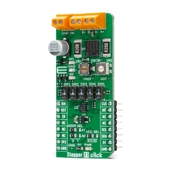
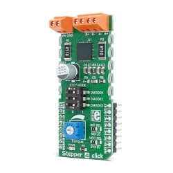
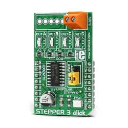
There are only four output stages connected on this Click board™, since the primary function of this Click board™ is driving a unipolar stepper motor. These outputs are equipped with the LEDs, which are used to indicate the state of every driver. These LEDs use their own power supply from the 5V mikroBUS™ power rail, so they will be lit whenever the corresponding driver is active, regardless of the connected load. The output stages are routed to the optional disconnectable crimp style XH connector with 2.5mm pitch, which can be used for connecting the 28BYJ-48, a small stepper motor suitable for a large range of applications. The fifth pin of this connector is the common wire of the motor coils, which is routed to the motor power source. For more information about how the stepper motor works, please follow the learn article link in the download section, below.
The motor coils can be supplied by either 5V from the mikroBUS™ or by an external power supply, connected to the input terminal. Selection between the external power supply and 5V rail from the mikroBUS™ is done by moving the jumper labeled as MOTOR PWR, to either 5V position or EXT position. This jumper is a 3x1 male header with the standard 2.54mm pitch, providing a simple and effortless operation.


Features & Specs
- Interface: GPIO
- Compatibility: mikroBUS™
- Dimensions: 42.9 x 25.4mm
- Input Voltage: 5V
- External Power Supply Voltage: Min. 5V, Max. 30V
- Current Limit (per channel): 500 mA
Documentation
Customer Reviews
Stock and Customer Discounts
Available Discounts
- $18.95 | 25+ units
- $17.96 | 100+ units