MIKROE RS232 Click
The main component of the RS-232 Click is the MAX3232, a 3.0V to 5.5V low power, true RS-232 transceiver, from Maxim Integrated.
Product Overview
RS232 Click provides an interface between the TTL/CMOS logic levels commonly used on microcontrollers and the RS-232 bus. RS-232 is a rather old communication protocol that has survived thanks to its robustness and implementation on many personal computer motherboards. It can still be found on various pieces of DTE and DCE equipment. This Click board™ allows standard type MCUs to communicate through the RS-232 interface via the standard UART bus pins: RX and TX. The RS-232 Click utilizes the MAX3232, a 3.0V to 5.5V low power, true RS-232 transceiver, from Maxim Integrated. This device can achieve communication speed up to 232 kbps (EIA/TIA-232).
A number of protection features improve the reliability of this device. It has up to ±15kV ESD protection, ensuring that no electrical discharge damages the circuit on the input side. The Click board™ offers voltage selection for interfacing with both 3.3V and 5V MCUs, allowing fast and reliable RS-232 communication for a wide range of MCUs. It can be used for any application that communicates using the low voltage RS-232 protocol.
The main component of the RS-232 Click is the MAX3232, a 3.0V to 5.5V low power, true RS-232 transceiver, from Maxim Integrated. This IC has two receiver and two transmitter channels, and it is used to bridge the physical differences between the CMOS/TTL signal levels and RS-232 bus levels. While CMOS/TTL signal levels vary from 0V to 5V typically, RS-232 uses the signal levels that range from ±5V, up to ±15 V. Furthermore, the RS-232 equipment is required to withstand short circuit for any voltage, up to ±25V, during an indefinite time interval. To interface CMOS/TTL signal level devices with the RS-232 bus, an adequate RS-232 transceiver, such as the MAX3232 has to be used. MAX3232 IC uses two internal charge pumps to obtain required driving levels of ±5V on its transceiver sections.
This Click board™ offers two inputs and two outputs which feature the CMOS/TTL logic levels. These lines can be used to either drive the RS-232 bus or receive the incoming data from the bus. Receivers convert the RS-232 signals to MCU acceptable UART type signal, while transmitters convert the MCU UART signal to RS-232 levels. Therefore one input/output pair is routed to the UART pins of the mikroBUS™, allowing simplified operation by the host MCU, while another pair of input/output signals is routed via the SMD jumpers and it is used as the RTS (Ready To Send) and CTS (Clear To Send). These pins are typically used for the UART communication with the hardware flow control. The jumpers are populated by default.
To achieve required driving levels, MAX3232 transmitters use the charge pumps, which use only two external capacitors for the proper operation. These capacitors, along with the two pull-up resistors, are the only external elements, required by the MAX3232 IC. If the RS-232 bus levels are driven beyond ±5V, these charge pumps are internally disabled. This means that the MAX3232 can drive the RS-232 bus with up to ±5V by itself. The MAX3232 device can maintain 120kbps data rate with the worst-case scenario - load of 3kΩ in parallel with 1000pF, while the typical communication speed goes up to 232 kbps.
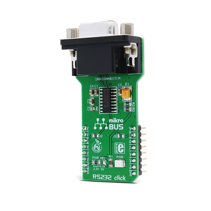
The Click board™ comes equipped with the SUB D connector, typically found on many devices that use the RS-232 interface. This connector can be used to connect the Click board™ directly to the RS-232 bus, offering RX, TX, CTS and RTS RS-232 signals.
RS232 Click can be used with both 3.3V and 5V MCUs. There is an SMD jumper labeled as PWR SEL, used to select the power supply voltage level, between 3.3V and 5V.


Features & Specs
- Interface: GPIO, UART
- Compatibility: mikroBUS™
- Dimensions: 57.15 x 25.4mm
- Input Voltage: 3.3V or 5V
Documentation
Customer Reviews
