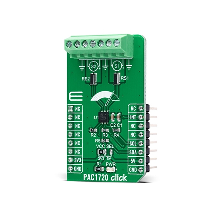
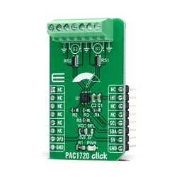
MIKROE PAC1720 Click
PAC1720 Click is a compact add-on board that contains an energy monitoring solution.
Product Overview
PAC1720 Click is a compact add-on board that contains an energy monitoring solution. This board features the PAC1720, an I2C configurable dual high-side bidirectional current sensing monitor with precision voltage measurement capabilities from Microchip Technology. The PAC1720 measures the voltage developed across external sense resistors to represent the high-side current of a battery or voltage regulator. They also measure the SENSE+ pin voltage and use these estimated values to present a proportional average power calculation. The current sensing feature includes fault protection, where during a fault condition, the ALERT pin can be asserted or masked. This Click board™ performs power calculations enabling energy monitoring in industrial and embedded applications, power management systems, and many more.
PAC1720 Click is supported by a mikroSDK compliant library, which includes functions that simplify software development.
PAC1720 Click as its foundation uses the PAC1720, a dual bidirectional high-side current-sensing device with precision voltage measurement capabilities from Microchip Technology. It measures the voltage developed across external sense resistors to represent the high-side current of a battery or voltage regulator, then digitizes it with a variable resolution Sigma-Delta ADC and transmits it over the I2C protocol. The PAC1720 also measures the SENSE+ pin voltages and calculates average power over the integration period.
The PAC1720 has three states of operation: Active, Standby, and One-Shot Mode. In Active mode, the PAC1720 initiates conversion cycles for the programmed conversion rate. The Standby mode represents the lowest power state, where there are no conversion cycles. The majority of circuitry is powered-down to reduce supply current to a minimum. While the device is in the Standby state, the host can initiate a conversion cycle on-demand using One-Shot mode. After the conversion cycle is complete, the device will return to the Standby state.
PAC1720 Click communicates with MCU using the standard I2C 2-Wire interface to read data and configure settings, supporting operation with a clock frequency up to 400kHz. Besides, it also allows the choice of its I2C peripheral address by positioning the SMD resistor of appropriate value labeled as R2, giving the user the ability to select one of eight possible peripheral addresses.
The current range allows for significant variations in measured current with high accuracy and the low voltage drop across the resistor. The PAC1720 has programmable high and low limits for current sense and bus voltage with a maskable alert signal labeled as INT, routed to the RST pin of the mikroBUS™ socket, to the host when an out-of-limit measurement occurs.
This Click board™ can operate with both 3.3V and 5V logic voltage levels selected via the VCC SEL jumper. This way, it is allowed for both 3.3V and 5V capable MCUs to use the I2C communication lines properly. However, the Click board™ comes equipped with a library containing easy-to-use functions and an example code that can be used, as a reference, for further development.


Features & Specs
- Interface: I2C
- Compatibility: mikroBUS™
- Dimensions: 42.9 x 25.4mm
- Input Voltage: 3.3V or 5V
- SENSE Pins Common-Mode Voltage Range: Min. 0V, Max. 40V
- Accuracy: ±1%
- Operating Temperature Range: Min. -40°C, Typ. +25°C, Max. +85°C
Documentation
Customer Reviews
Stock and Customer Discounts
Available Discounts
- $14.20 | 25+ units
- $13.46 | 100+ units