MIKROE Current 7 Click
Current 7 Click is a compact add-on board providing a precise and accurate current sensing solution.
Product Overview
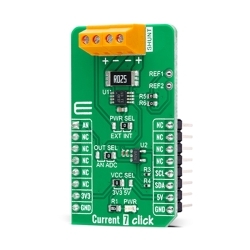
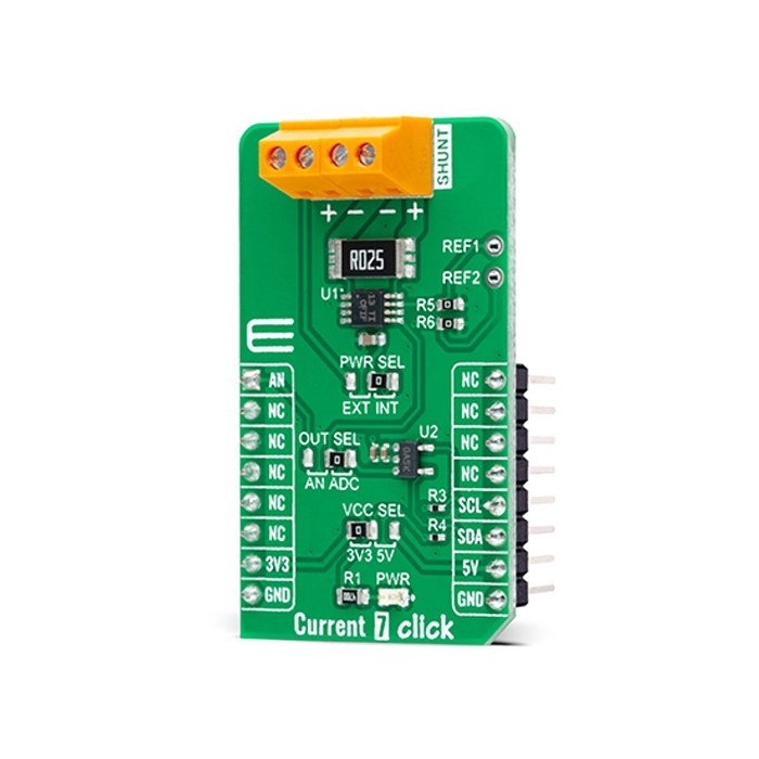
Current 7 Click is a compact add-on board providing a precise and accurate current sensing solution. This board features the INA282, a wide common-mode range, bidirectional, high-accuracy current shunt monitor from Texas Instruments. The INA282 represents a voltage output current shunt monitor that can sense drops across shunts at common-mode voltages from –14 V to +80 V, independent of the supply voltage, which operates in a range from 2.7V up to 18V supply. The zero-drift topology enables high-precision measurements with maximum input offset voltages as low as 70μV. Also, the user is allowed to process the output signal in analog or digital form. This Click board™ delivers higher performance to industrial control and automation applications, load and power supplies monitoring, telecom equipment, and many more.
Current 7 Click is supported by a mikroSDK compliant library, which includes functions that simplify software development.
Current 7 Click as its foundation uses the INA381, a high-accuracy current-sensing amplifier from Texas Instruments. This voltage output current-sensing amplifier accurately measures voltages developed across the current-sensing resistor (also known as a current-shunt resistor) at a common-mode range that extends 14V below the negative supply rail as up to 80V, allowing for either low-side or high-side current sensing. The zero-drift topology enables high-precision measurements with maximum input offset voltages as low as 70μV over the entire temperature range of –40°C to +120°C.
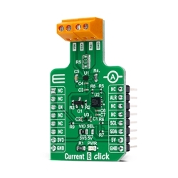
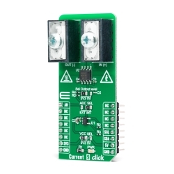
This Click board™ possesses two ways to communicate with the MCU. The analog output signal of the INA282 can be converted to a digital value using MCP3221, a successive approximation A/D converter with a 12-bit resolution from Microchip using a 2-wire I2C compatible interface, or can be sent directly to an analog pin of the mikroBUS™ socket labeled as AN. The MCP3221 provides one single-ended input with low power consumption, a low maximum conversion current, and a Standby current of 250μA and 1μA, respectively. Data can be transferred at rates of up to 100kbit/s in the Standard and 400kbit/s in the Fast Mode. Selection can be performed by onboard SMD jumper labeled as OUT SEL, setting it to an appropriate position marked as AN and ADC.
The INA282 also allows a connection of external voltage signals on the onboard headers labeled as REF1 and REF2 for the device’s reference voltage. This reference voltage determines how the output responds to certain input conditions. The configurable settings of the reference voltage control resistors, R5 and R6, allow the INA282 to be used in unidirectional and bi-directional applications. More information about these operational modes can be found in the attached datasheet.
This Click board™ can operate with both 3.3V and 5V logic voltage levels selected via the VCC SEL jumper. It allows for both 3.3V and 5V capable MCUs to use the communication lines properly. Additionally, there is a possibility for the INA282 power supply selection via jumper labeled as PWR SEL to supply the INA282 from an external power supply terminal in the range from 2.7V to 18V or with mikroBUS™ power rails. However, the Click board™ comes equipped with a library containing easy-to-use functions and an example code that can be used, as a reference, for further development.


Features & Specs
- Interface: Analog, I2C
- Compatibility: mikroBUS™
- Dimensions: 42.9 x 25.4mm
- Input Voltage: 3.3V or 5V, External
- Supply Voltage VCC: Min. 3.3V, Max. 5V
- External Supply Voltage VEXT: Min. 2.7V, Max. 18V
- Common-Mode Voltage Range: Min. -14V, +80V
- Gain: 50 V/V
- Operating Temperature Range: Min. -40°C, Typ. +25°C, Max. +120°C
Documentation
Customer Reviews