SparkFun USB to RS-485 Converter

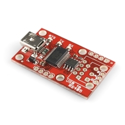
This is the newest revision of this board and this breakout board pairs an SP3485 RS-485 transceiver with an FT232RL USB UART IC to convert a USB stream to RS-485. The SP3485 is a half-duplex transceiver, so it can only communicate one way at a time, but it can reach transmission speeds of up to 10Mbps.

The TXDEN pin of the FT232RL is connected to the transmit and receive enable inputs of the SP3485, this line is used to control the transmission mode of the RS-485 transceiver. With the proper drivers installed, the FT232RL will enumerate as a virtual COM port; the drivers are available for Windows, Mac and Linux.

This breakout board includes the SP3485, FT232, TX/RX/RTS LEDs, Mini-B USB connector, filter capacitors, and other components shown on the schematic. We've broken out the RS485 output to three different connections: (1) an RJ-45 connector, (2) a 3-pin 3.55mm screw terminal, and (3) a 3-pin 0.1" pitch header; none of these output connectors come populated.

  • Fully equipped with SP3485 RS-485 transceiver and FT232RL USB UART IC
  • Operates from USB supply
  • RX, TX, and RTS LED indicators
  • Mini-B USB connector
  • USB power and RX/TX lines broken out to a 0.1" pitch header
  • RS-485 input/output broken out to RJ-45 connector, 3.5mm screw terminal, and 0.1" pitch header
  • Driver/Receiver Enable connected to RTS line of FT232RL
  • -7V to +12V Common-Mode Input Voltage Range
  • 1.55x0.9 inches

SparkFun USB to RS-485 Converter Product Help and Resources

AST-CAN485 Hookup Guide

March 1, 2018

The AST CAN485 is a miniature Arduino in the compact form factor of the ProMini. In addition to all the usual features it has on-board CAN and RS485 ports enabling quick and easy interfacing to a multitude of industrial devices.

Dimensions

Measuring with the caliper, here are some dimensions:

width = ~23.57mm (one side of PCB to the other side of the PCB)

length = ~40.40mm (end of the PCB to the edge of the mini-B connector)

height = 1.65mm (measured from the bottom of the PCB to the top of the PCB)

maximum height = (~5.71mm from the bottom of the PCB to the top of the mini-B connector)


Core Skill: Soldering

This skill defines how difficult the soldering is on a particular product. It might be a couple simple solder joints, or require special reflow tools.

1 Soldering

Skill Level: Noob - Some basic soldering is required, but it is limited to a just a few pins, basic through-hole soldering, and couple (if any) polarized components. A basic soldering iron is all you should need.
See all skill levels


Core Skill: Electrical Prototyping

If it requires power, you need to know how much, what all the pins do, and how to hook it up. You may need to reference datasheets, schematics, and know the ins and outs of electronics.

2 Electrical Prototyping

Skill Level: Rookie - You may be required to know a bit more about the component, such as orientation, or how to hook it up, in addition to power requirements. You will need to understand polarized components.
See all skill levels


Comments

Looking for answers to technical questions?

We welcome your comments and suggestions below. However, if you are looking for solutions to technical questions please see our Technical Assistance page.

  • Lutorm / about 5 years ago / 1

    Does anyone know what the delay of this converter is, ie what's the time between sending to the usb port and bits getting clocked out over the rs485? My application doesn't need a lot of bandwidth, but it is latency sensitive.

  • I bought 1 SparkFun FTDI Basic Breakout - 3.3V, 1 SparkFun Transceiver Breakout - RS-485 and 1 SparkFun USB to RS-485 Converter .

    I connect:

    PC1 -> FTDI Basic Breakout -> Transceiver -> USB to RS-485 -> PC2.

    To communicate PC1 to PC2, I connect TXDEN (FTDI Basic Breakout ) to RE/DE (Transceiver). If I send "Hello PC2" message, in PC2 I receive " Hello PC2<0>".

    To communicate PC2 to PC1, if I send "Hello PC1" message, in PC1 I receive " Hello PC1" but in PC2 I receive many bytes of trash. The same trash come if RS485 modules are not connected.

    I suspect that SparkFun USB to RS-485 Converter is damaged, but its new...

    Anyone else had this issue?

  • Read for quick and easy fixes! My adapter did not work correctly out of the box. The TX and RX LEDs are reversed as I would expect to see TX LED pulse when sending data to the 485 bus. The CTS# line is unconnected and therefore internally pulled high. The CTS line being high prevents the UART from sending data as the CTS line is the counterpart for RTS/CTS flow control. You could solder pin 11 to ground or better yet, I recommend users perform the following EEPROM change to the FT232RL using the FTDI FT_Prog utility (http://www.ftdichip.com/Support/Utilities.htm).

    • Plug USB to 485 adapter in
    • Devices -> Scan and Parse (Ensure you have the correct device if you have a number connected. If in doubt, disconnect others)
    • FT EEPROM -> Hardware Specific -> Invert RS232 Signals -> (check) Invert CTS#
    • FT EEPROM -> Hardware Specific -> IO Controls -> C0 (select) RXLED#
    • FT EEPROM -> Hardware Specific -> IO Controls -> C1 (select) TXLED#
    • Devices -> Program
    • Cycle the USB device (unplug and re-plug)

    Select Hardware Flow Control (RTS/CTS) in your favorite program or library and away you go!

  • Cyphus / about 13 years ago / 2

    Has anyone else managed to get this to work for DMX-512? I have it set up with openDMX controller software, but the very second I hook it into the DMX system it causes a blackout.
    This board seems to have the same circuits as many others online (except for some protection circuits missing) and I see no reason why it shouldn't work.

    • Alexander Donohue / about 11 years ago * / 1

      Really late reply, I hope you got your issue fixed. I figured that this may be of some use to others. I am using this for my lighting system. I am using Q Light Controller (http://qlc.sourceforge.net/) This board is functionally the same as the ENTTEC Open DMX USB Interface. In fact I use the same drivers with the board. They are available on the ENTTEC website under Downloads->'Drivers Setup' (http://www.enttec.com/index.php?main_menu=Products&pn=70303&show=downloads)

      • Member #617202 / about 9 years ago / 1

        Sorry for comment on an old comment, hopefully you'll see this. Did you have to do any of the reprogramming that these comments mention in order for this to work with DMX? Or did it just work out of the box for you?

        • Member #630412 / about 9 years ago / 1

          I just got the newer 09822 board and pretty much works out of the box for QLC+ ( Q Light Controller plus) software. The terminating resistor on the board is 220 ohm. I added a 220 ohm resister in parallel across A and B to get the approximate DMX termination value of 110 ohm. I soldered the resistor between pins 7 and 8 on the RJ45 connector holes. I used the FTDI CDM drivers on Windows XP. QLC+ detected the board and once you map it as output in your DMX universe, the red LED starts flashing. For all intents and purposes, this board should look like an OpenDMX interface. Lights go on and off and dim as expected in QLC+.

    • mitchmao / about 12 years ago / 1

      I was planning to use this for OpenDMX application as the new Arduino UNO ditched the FT232 chip. Where you able to get the thing to work? Contact appreciated =)

  • Member #731543 / about 9 years ago / 1

    I have a set of Modbus RTU RS485 slave controllers. I need to read/write from/to these controllers using an application on a PC. would this converter do the job?

  • Member #731543 / about 9 years ago / 1

    I have a set of slave controllers running on MODBUS RTU(RS-485). I need to read/write data from/to these controllers using a GUI on a PC. would this do the job?

  • Member #662492 / about 9 years ago / 1

    Can this work at both ends - I have a simple USB temperature box that connects to a computer. I need to run this over a long distance so would like to go from USB to rs-485 and back to USB. I'm not sure if this board will work without a computer and kernel driver

    • jma89 / about 9 years ago / 1

      You'll need something to talk USB on both sides, so yes, your remote device would need to be a USB host and have the proper drivers for talking with this chip.

      Is this temperature box pre-purchased or something you built? There are other options for doing USB over vast distances (active extenders, Ethernet (as in IP) adapters, etc), but they each have their pros and cons.

  • Member #203383 / about 9 years ago / 1

    Ive build a small housing for this adapter: http://www.thingiverse.com/thing:540898

    Greetings Klaus

  • Member #359298 / about 10 years ago / 1

    The description above is a bit misleading. It seems to imply you can use this device up to 10 MHz baud rate (i needed 6 MHz). After a bit of digging I discovered the FTDI chip only goes to 3 MHz baud rate. I guess the comment is about the RS484 converter part only.

    Sparkfun, you really should fix the wording in the description since we now have a half a dozen of these laying around with no home.

  • Oronymo / about 10 years ago / 1

    I'm considering using this to control the MondoMatrix which is basically a multi-motor version of an Arduino board that communicates via RS-485. I'm wondering what an appropriate programming environment / application on Windows might be for controlling via this device?

  • Member #523560 / about 10 years ago / 1

    can someone tell me where can I find this in the Sparkfun Eagle libraries ????

  • pratikshinde / about 11 years ago / 1

    The RTS pin of the FT232RL is connected to the transmit and receive enable inputs of the SP3485

    However schematic shows, TXDEN is connected to RE and DE. Which is correct?

  • tantivy / about 11 years ago / 1

    One suggestion I have is to bring pins 4/5 on the "RJ45" (don't get me started about incorrect use of RJ nomenclature) out to JP12, and put ground pads adjacent to them. That way you can easily use the third pair for other things if you don't need the ground, or jumper across if you do. Maybe add pads for the shield of a shielded "RJ45" while you are at it. The same comment would apply to BOB-10124.

  • Skye / about 13 years ago / 1

    /RE and DE should not be connected. If they are it is NOT possible to perform bus contention testing on a multidrop system. If two transmitters were to send at the same time, the only way they know if there was a collision is to read back what they sent to make sure they are the same. The way you have it implemented, enabling the transmitter disables the receiver! I hope I can modify the board to always enable the receiver, if not, it will have to be returned.

    • adamj537 / about 11 years ago / 1

      Most commercial USB-to-RS-485 adapters are built with the /RE and DE connected, since RS-485 is half-duplex (you can either send or receive, but never both at the same time). This allows a single pin of a microcontroller (or the TXDEN pin of an FTDI chip) to control both receive and transmit enables at the same time. Wiring the adapter so both the transmitter and receiver are enabled at the same time will cause any characters transmitted to be "echoed" back, which is only desirable for custom applications where software can distinguish between an echo and a response from another device.

      If bus contention is an issue, try using a protocol where each device has a unique address, a "master" device transmits to the other "slave" devices, and then each slave transmits after a fixed time interval multiplied by their address...so no one talks at the same time. If you truly need full duplex communication, consider using two RS-485 transceivers (and four wires).

      • Skye / about 11 years ago / 1

        I suppose this is a matter of taste, but most systems that use RS-485 in the military world use it because it allows for a multidrop system with limited number of wires. In such systems it is important/critical to know if you have had a bus collision. For this reason, the receiver is always left on. When you transmit, you read back what you wrote. If they are the same, great; if not, you had a collision and must rebroadcast. Very similar to Ethernet.

        If in the commercial world RS-485 is only used for single duplex single master to slave setups then their implementation is fine. Otherwise I contend they have their heads in a dark place.

        Not that Sparkfun reads these comments (its been two YEARS since I posted), but if they do, I would suggest the next revision of the board include a solder jumper to allow for a "receiver always on" mode. By default it would connect the /RE and DE as right now. Add or remove the solder jumper and the recieve enable would be enabled and the transmit enable would go back to the micro. Should only add the cost of one resistor and a bit more copper.

        As for considereing other options, I would love to, but I am dictated by my customer. Its been a while, but I think I was able to lift the receiver enable pin and tie it appropriately.

        • adamj537 / about 11 years ago / 1

          Kudos to you for replying to a two-year old comment! I meant my remarks as sort of a clarification to others who read comments (and didn't realize there was a customer involved who would dictate communication methods). Perhaps you're right about the jumper.

  • I got mine today and they worked fine once I swapped A & B on the RS 485 end. The Rx and Tx lights are also backwards for my application.

  • Member #233818 / about 13 years ago / 1

    I need more throughput than this chip will provide. That is, Larger TX and RX buffers on the chip. Anyone know where I can get a USB to RS485 converter with a larger buffer?

  • Member #62690 / about 13 years ago / 1

    Yeah I agree TX & RX are swapped.

  • c.fowler / about 13 years ago * / 1

    1a: Fixed termination resistor is a bad idea.
    1b: The termination resistor is the wrong (common) value.
    2: DE should be tied to TXDEN!
    3: Don't tie /RE to DE on the SP3485. (Some of us like to hear what we say...)
    I can't believe all the RS485 break-outs (at the time of writing this) suffer from 1 and 3...

  • Member #27638 / about 13 years ago / 1

    Correct me if I'm wrong, but the TX and RX markings seem to be mixed up on the Silk screen on the newest version (BOB-09822)?
    Other than that its a nice little board. Just started using it with PySerial :)
    Cheers!

  • bikeNomad / about 13 years ago / 1

    The description above

    Driver/Receiver Enable connected to RTS line of FT232RL
    is incorrect; the enables are in fact connected to one of the GPIO lines of the FT232RL (pin 13, CBUS2/TXDEN).
    This is what most people want; it means that you don't need special application-layer support for turning on RTS to transmit.
    If you have an application that insists on turning on RTS it should also work fine.

  • dlbsmith / about 14 years ago / 1

    Has anyone tried to connect one of these to the RS-485 Breakout sku: BOB-09823?
    I have an RS-485 Breakout connected to a Fez Domino and I am trying to communicate through RS-485 to a PC.
    We have scoped out the RS-485 line and transmitted data in both directions looks fine.
    If we connect a different RS-485 device from a different manufacturer then we can communicate to it in both directions.
    So the issue seems to be communicating between two SP3485 based devices.
    We have tried adding additional bias resisters similar to those on the other device. But it does not help.
    Our best guess is that the issue is related to the 3.3V operation and the fact that each one has a terminating resister. Since an RS-485 network should really not have multiple termination resisters we wonder if this is the problem. Before I start modifying a board I wanted to see if anyone else had sucess with this setup.
    As a product suggestion: a switch or jumper to disconnect the termination resister.

  • AaronCarlton / about 14 years ago / 1

    Schematic PDF and Eagle files are for RS485 driver board, not the USB to rs485 converter board. (FTDI Chip is not in the schematic, but is on the board in the picture)

  • electrokean / about 14 years ago / 1

    So does this version use RTS or the FTDI TXDEN signal to enable the SP3485 driver ?
    The schematic seems to still be for the original version of the board.

    • Sorry about that! Fixed.

      • Cory78 / about 14 years ago / 2

        But you didn't fix the description describing your change... just cost me many hours of time :(
        "Driver/Receiver Enable connected to RTS line of FT232RL"

Customer Reviews

3.7 out of 5

Based on 7 ratings:

Currently viewing all customer reviews.

Does precisely what it should.

Simple. Straightforward. Just hook it up per the pinout and go. Add a RJ45 and make it easier.

Schematic vs description?

The description states "Driver/Receiver Enable connected to RTS line of FT232RL" but the schematic shows that the driver receiver/receiver enable is connected to TXDEN. Which is it?

Serious problems with this product

I bought 10 Pc. Three of the units work ok. Seven of them do not work.

I have checked the converters with an oscilloscope and a multimeter. In the bad pieces, level of Rx pin of the SP3485 is low, and when data arrives goes to high without following the incoming data. Resistance between Vcc and Rx pins is infinite. In the good pieces, level of Rx pin is high, and when data arrives follows data correctly. Resistance between Vcc and Rx pins is high, but not infinite.

I wait for your comments Regards Daniel

Hmm, this is not an issue we've seen before. I'll do some testing on some boards, and contact you directly to resolve this for you.

Didn't work

Bought this to interface an RS-485 sonar I purchased. Loved the price and size, but I had intermittent communications issues. Neither Sparkfun nor the sonar company could help me get it to work. Ended up buying a more expensive converter from another company which worked perfectly.

Works very good

It has been working for over 3 months, no issues. I'm using it to communicate a Raspberry with a driver of a huge motor that powers a fan.

Tx and Rx LED silkscreen seems to be wrong

The schematic says TX is red and Rx is green but on my board the silkscreen TX and RX marks seem to be on the wrong LEDs. When the board transmits the red LED with silkscreen label RX lights up, while when the board receives, the green LED labelled TX lights up.

Apart from that the board is great.

The LEDs follow traffic on the RS-485 side of the board rather than the traffic on the USB side so they will appear backwards from what you're expecting.

DMX Controller

This works wonderfully for testing dmx setups.