- Home
- Product Categories
- Sensors
- IMU Analog Combo Board Razor - 6DOF Ultra-Thin IMU

IMU Analog Combo Board Razor - 6DOF Ultra-Thin IMU
Replacement:SEN-10121. This board has been replaced by the IMU Digital Combo Board. This page is for reference only.
This new version of the board removes the high-pass filters which were creating some issues with the output.
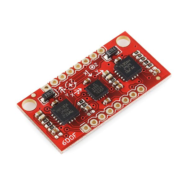
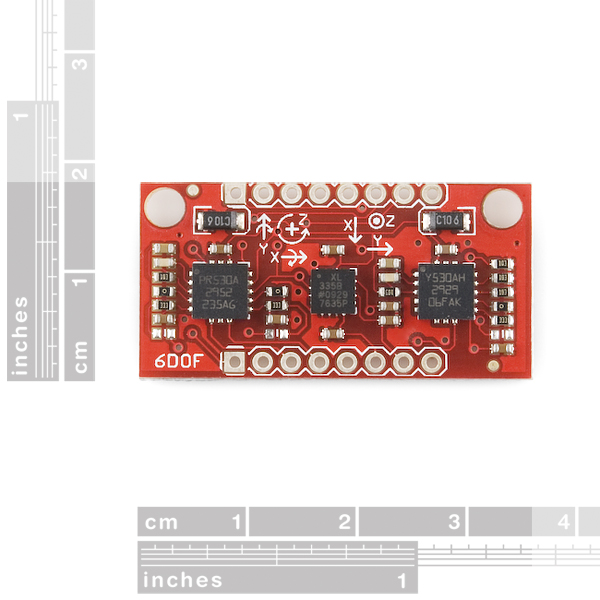
There's a lot of punch packed into this little IMU. The 6DOF Razor makes use of ST's LPR530AL (pitch and roll) and LY530ALH (yaw) gyros, as well as the popular ADXL335 triple-axis accelerometer, to give you six degrees of measurement on a single, flat board.
All analog outputs of the gyros (1x and 4x amplified) and accelerometer are broken out to the 0.1" pitch headers. The gyro outputs have a full scale of ±300°/s, while the outputs of the accelerometer have ±3g range.
There is no on-board regulation, so you'll need to provide a clean 3.3VDC power source, which will power all three sensors. All filtering capacitors and other components are included as shown on the pictures.
**Replaces: **SEN-09431
- 2.7-3.6VDC power supply
- Low power consumption
- Pitch, yaw, and roll gyro outputs
- 1x and 4x amplified (0.83 and 3.33 mV/°/s sensitivity, respectively)
- ±300°/s range
- x-, y-, and z-axis accelerometer outputs
- 300mV/g sensitivity
- ±3g range
- All necessary filtering components
- Access to gyro's self-test, power-down, and high-pass filter reset pins
Comments
Looking for answers to technical questions?
We welcome your comments and suggestions below. However, if you are looking for solutions to technical questions please see our Technical Assistance page.
Customer Reviews
No reviews yet.
Great board! I'm using it to develop my own UAV. I've posted Arduino code for fusing the data and displaying it on an attitude indicator program, which I also made(its available for download). All can be found HERE.
Sir, I also want develop a similar project as you have stated ie. a UAV or an autonomous plane.... I have good command on c programming of atmega controllers . I'm new in world of arduino but found it quite easy . So surely would be using arduino for my project . I have a idea of how can I put a autonomous system into a plane . But I need help .... Sir , please give me whatever information you have ie. code snippets ,algorithms, equtions anything .... I will be very thankful to you
I made a guide on how to use this IMU with the Arduino including a Kalman filter:
Guide to gyro and accelerometer with Arduino including Kalman filtering
Hi, I have a 1"x 1" small PCB that does 6 degrees of freedom on batch PCB.
http://batchpcb.com/index.php/Products/51805
I2C interface
How come this board doesn't align the x and y axis on each sensor? From the readings, you could program the micro controller accordingly, but it seems better if the X and Y were aligned.
It's one of several different coordinate schemes:
This board has the X and Y angle set up so that a positive X angle tilt will result in a positive linear acceleration (and displacement) along the X axis, and a positive Y angle tilt will result in a positive acceration along the Y axis.
It seems like this was more intended for quadrotors and helicopters than for airplanes and other craft.
Out of curiosity, what is the reccomended samping rate for this board?
From looking at the schematic (and referring to the supplied datasheets), I see that the Gyro's have a -3dB LPF at around 48Hz and the Accelerometers have a -3dB LPF at 50Hz.
I'm currently running the ADC at a rate of 110Hz, and I'm worried that I might be sapping some performance and/or introducing noise...
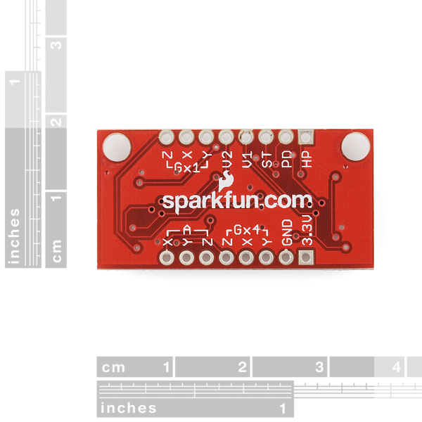
I have a couple of questions about the pins:
- why are there two voltage pins? V1 and V2
- What is the 3.3V pin for and what should it be connected to
what input current can be safely given to the IMU?
From the schematic, the V1 and V2 pins are VREF's for the gyro chips. I don't use these, and the data sheet indicates to use the VREF's if using only the non-amplified outputs.
As for what pins to use, use the 3.3V pin for power. Use the GND pin for ground. I also use the Gx4 gyro pins and the accelerometer pins next to those. I don't use any pins on the other side of the board.
Has anyone encountered problems with z-axis gyro reading? For some reason when I connect to the 4x output, the stationary reading oscillates at 1.2 +/- 0.1 V at 87Hz (sensitivity is only 3.33mV/deg, so I'm reading crazy values), while x and y readings are perfectly accurate.
Yes, I dont get anything useful out of it either in the Z. Also, Im guessing no-one has tried with a Li-Poly battery as these are 3.7v which is likely too much. Maybe a diode would help there?
can anyone tell me how im able to interface the gyros with the accelerometers in this board??
im trying to make an inertial navigation system by connecting this board with an arduino and im really lost. could really do with some help!
Check my guide out. It is based on this IMU: Guide to gyro and accelerometer with Arduino including Kalman filtering
is this compatible with xbee or zigbee or any other wireless like bluetooth? if not please tell me a good imu + wireless solution!
is razor 9 dof + bluetooth mate ok?
i need to make a 3d mouse pointing device using that!
please help thanks.
Works well for angular positioning, but the gyros idle a bit lower than the accelerometer... when reading these from my Arduino via the 10-bit Analog inputs (with Aref tied to 3.3v), the accelerometer outputs centered right at 512 when "level" (scale of 0-1023) - while the gyro outputs all centered around 390 (when sitting still)? I thought this was a bit odd, but it is also stated in the datasheet that center voltage for gyros is 1.23v.
By combining the X outputs from both accel and gyro to my Arduino, I made a weighted complementary filter to control a Segway type ridable bot. It works great!
All Gyros exhibit this behavior. It's called gyro drift. You have to calibrate it out. Also the drift will vary over temperature. The big downside I see to this IMU is no temperature readings. You may test your quadrotor inside and everything is fine. then take it outside in the Hot or Cold and it will behave differently because the sensor reading will vary some based on temperature.
Perfect! thanks! Just ordered one!
~long live the sparkfun
Someone has problem with the Gyros, or it's just me, I can't integrate the speed to obtain the position.
What is the output of this board? analog or digital signals?
thanks
Analog my friend.
Has Anyone tried this IMU?
What do you think about this IMU in a Quadrotor???
Hi!
He's not bad for quadrotor, but you must use Kalman filter for coupling accelerometer output with gyro output. And be carefull with the number of output, because he ask 6 analog input for reading, maybe we don't have enought free on your board coupling with other sensors, for example adding magneto ...
@ Racine : Hi, any help re how to integrate (Kalman filter) for a quad rotor. Apart from that, the Z-axis value is not similar to the X and Y since it is +30 more than the latter
Is there any reason to go for this one instead of a ITG-3200 breakout + ADXL335 breakout which actually turn out to be slightly cheaper(?!)