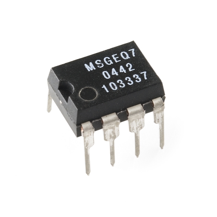
Graphic Equalizer Display Filter - MSGEQ7
Helpful Documentation
 Datasheet
Product Overview
The seven band graphic equalizer IC is a CMOS chip that divides the audio spectrum into seven bands. 63Hz, 160Hz, 400Hz, 1kHz, 2.5kHz, 6.25kHz and 16kHz. The seven frequencies are peak detected and multiplexed to the output to provide a DC representation of the amplitude of each band. No external components are needed to select the filter responses. Only an off chip resistor and capacitor are needed to select the on chip clock oscillator frequency. The filter center frequencies track this frequency.
Other than coupling and decoupling capacitors, no other external components are needed. The chip supply can be between 2.7 and 5.5 volts with 5 volts providing the best performance. The device has very low quiescent current (less than 1ma typical) for portable audio devices. the multiplexer is controlled by a reset and a strobe, permitting multiplexer readout with only two pins. The multiplexer readout rate also controls the decay time (10% decay per read), so no external pins are needed for this function.


Features & Specs
- Low Power Consumption
- Only Two External Components
- On Chip Ground Reference
- Switched - Capacitor Filters
- 3.3 or 5 Volts Operation
- 20 dB of Gain
- On Chip Oscillator
- Output Multiplexer
- Variable Decay Time
- 8 Pin DIP Package
Documentation
Customer Reviews
