- Home
- Product Categories
- GPS Boards
- SparkFun Venus GPS Logger - SMA Connector

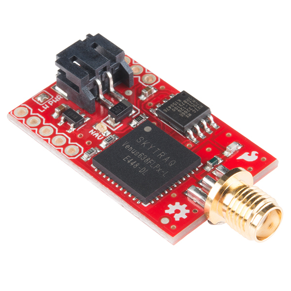
SparkFun Venus GPS Logger - SMA Connector
The smallest, most powerful, and most versatile GPS receiver we carry just got more powerful. The Venus638FLPx is the successor to the Venus634LPx and has improved sensitivity and a faster update rate. The new module can be configured to an amazingly powerful 20Hz update rate. With 29mA operating current and high sensitivity, this receiver seriously opens new doors for tracking. Module outputs the standard NMEA-0183 or SkyTraq Binary sentences at a default rate of 9600bps (adjustable to 115200bps).
The Venus638FLPx has improved sensitivity, an integrated LNA (with multipath detection and suppression), built-in RTC, and integrated single power supply making it very simple to use.
Not sure which GPS module is right for you? Check out our GPS Buying Guide!
- 20Hz Update Rate
- 1Hz Logging Rate
- -148dBm cold start sensitivity
- -165dBm tracking sensitivity
- 29 second cold start TTFF
- 3.5 second TTFF with AGPS
- 1 second hot start
- 2.5m accuracy
- Multipath detection and suppression
- Jamming detection and mitigation
- SBAS (WAAS / EGNOS) support
- 67mW full power navigation
- Works directly with active or passive antenna
- Supports external SPI flash memory data logging
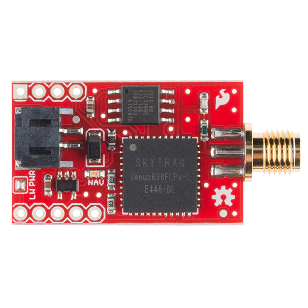
- IC 32M Serial Flash Memory
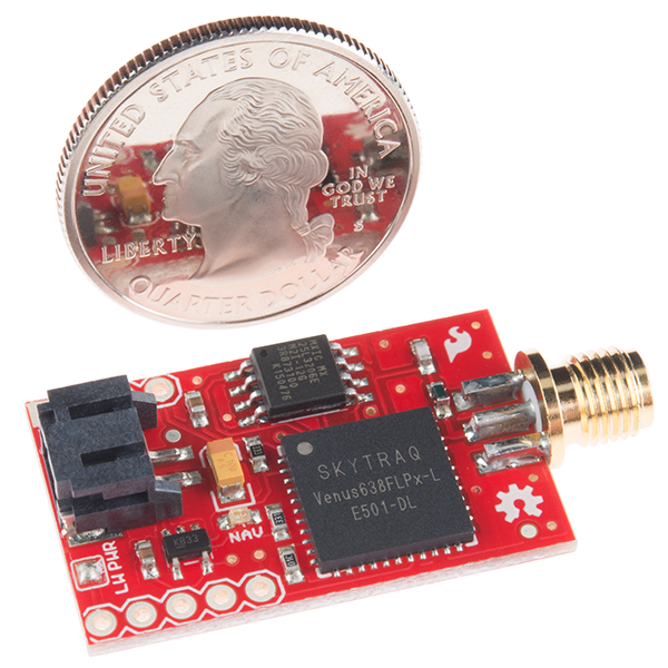
- Complete receiver in 10mm x 10mm x 1.3mm size
- Contains LNA, SAW Filter, TCXO, RTC Xtal, LDO
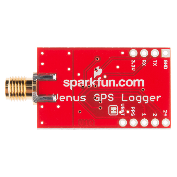
- Can be powered by a 3.7V LiPo battery (or any 3.5 - 12V supply) through the JST connector or 3.3V regulated supply.
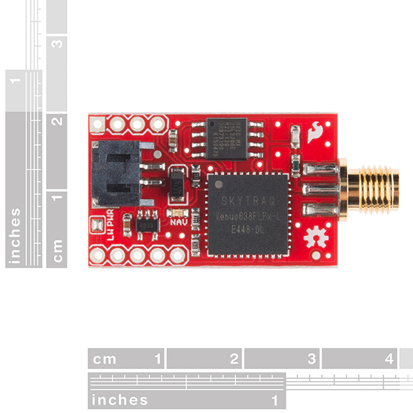
- 1.25 x 0.75 inches
SparkFun Venus GPS Logger - SMA Connector Product Help and Resources
1 of 1 found this helpful:
GPS giving you the wrong location?
Some customers have been found to confuse the indication given by the sensor thinking that it was in “decimal degrees” but it is in “degrees decimal minutes” notation. This mistake gives a perfect 40Km offset in the interpretation of the position. So the sensor works well, the mistake was in the interpretation of the given data.
How to use the logger functions
First, you must use the SkyTraq software we have on the product page.
1- Connect a LiPo battery to the JST connector, OR an external 3.3 volt DC power supply. (Don't use a 3.3 volt FTDI breakout for power, it can't supply enough current. The Beefy 3 should be OK)
2- Download and install the SkyTraq 0.4.833 software from the product page.
3- Connect a 3.3 volt FTDI breakout (or other 3.3 volt USB to serial converter.) to the GND, RX and TX pins on the Venus GPS.
4- Start the SkyTraq software, select the COM port your FTDI breakout is on. Set the baud rate for 115200 and then click the "Connect" button. You should start seeing NMEA data scroll by in the message window.
5- Go to the "DataLog" menu at the top of your screen and select "Log Configure." Change any options you want to. I find that the defaults work well.
6- At the bottom of the Log Configure Control window, select "Enable" for the "DataLog:" option, then click the button labeled "Settings"You should see "Log Configure Control Successful" appear in the Response window.
7- If you want to start with a fresh empty log, go back to the "DataLog" menu and select "Log Clear." You should see "Log Clear Control Successful" in the Response window.
8- At this point, your Venus is logging data to it's onboard memory. Take the GPS with you on a nice hike, or a short drive around the block. To retrieve that data follow the next steps.
9- Reconnect your Venus to a computer with a FTDI cable like you did before, then follow step 4 to get SkyTraq ready to download new data.
10- Go to the "DataLog" menu and select "Log Read Batch." The software will prompt you to save the accumulated data to a file on your computer. Click save to do that.
11- At this point, you have downloaded a compressed version of your stored GPS data to your computer. In order to convert that to use able data, you need to do one more step.
12- To convert that data file, go back to the "DataLog" menu and select "Log Decompess." The SkyTraq software will ask for the file you just downloaded. Select that file, then click on save. A window saying "Decompress is completed!" should appear. Click OK.
13- In the same folder you downloaded the GPS data, you will now find three new files. a .logg file that contains human readable positional data, a .nmea file that has raw NMEA GPS data in it, and a .kml file that can be loaded up in Google earth showing your journey.
Core Skill: Soldering
This skill defines how difficult the soldering is on a particular product. It might be a couple simple solder joints, or require special reflow tools.
Skill Level: Noob - Some basic soldering is required, but it is limited to a just a few pins, basic through-hole soldering, and couple (if any) polarized components. A basic soldering iron is all you should need.
See all skill levels
Core Skill: Programming
If a board needs code or communicates somehow, you're going to need to know how to program or interface with it. The programming skill is all about communication and code.
Skill Level: Rookie - You will need a better fundamental understand of what code is, and how it works. You will be using beginner-level software and development tools like Arduino. You will be dealing directly with code, but numerous examples and libraries are available. Sensors or shields will communicate with serial or TTL.
See all skill levels
Core Skill: Electrical Prototyping
If it requires power, you need to know how much, what all the pins do, and how to hook it up. You may need to reference datasheets, schematics, and know the ins and outs of electronics.
Skill Level: Competent - You will be required to reference a datasheet or schematic to know how to use a component. Your knowledge of a datasheet will only require basic features like power requirements, pinouts, or communications type. Also, you may need a power supply that?s greater than 12V or more than 1A worth of current.
See all skill levels
Comments
Looking for answers to technical questions?
We welcome your comments and suggestions below. However, if you are looking for solutions to technical questions please see our Technical Assistance page.
Customer Reviews
4 out of 5
Based on 4 ratings:
2 of 2 found this helpful:
Very Useful,accurate, fast acquisition, some quirks
I bought this to connect with my weather station shield. I had to figure out which wires from the jumper would be 3.3V, TX,RX,GND. Not that hard, I just wish I had more info readily available. There is little info on the board pins labeled 1, 2, 24. I found it in the comments from the previous version of the board.
I want to be able to put the chip into low power mode once a I get the date and time. I bought it for time sync and works well for that purpose.
0 of 2 found this helpful:
Jack Simmons
Hi Folks, I am only the buyer but I sent the review on to the engineer it was bought for. Thanks, Jack
Works well, not much documentation.
Once I got it working, it returned correct data, but getting it to work took some... work. Most of the code I got online was confusing, and there is basically no documentation. The problem I was having was that the Tx from the GPS needs to go to the Rx on the Arduino, and vis versa. Once I did this, the code I got from the internet worked, but nobody told me I had to switch those two (I found it casually mentioned on a YouTube video). It works well, but documentation would be really nice.
Very easy to use and connect to a microcontroller
Although I didn't find any info how to connect this module to an Arduino I just started by programming the Arduino to Serial.read() data at 9600 bps and send the output to the Serial monitor and it worked. I did have to move from the basement to the main floor of the house to get GPS Data. The module will flash when GPS data is received. Also, unless you plan on using the logger software with an FTDI cable there's no need to use the Rx input on the Venus GPS Module.
How to use the logging capability on the Venus GPS Logger.
First, you must use the SkyTraq software we have on this product page.
1) Connect a LiPo battery to the JST connector, OR an external 3.3 volt regulated DC power supply. (Don't use a 3.3 volt FTDI breakout for power, it can't supply enough current. The Beefy 3 will work for both power and data though.)
2) Download and install the SkyTraq 0.4.833 software from this product page.
3) Connect a 3.3 volt FTDI breakout (or other 3.3 volt USB to serial converter.) to the GND, RX and TX pins on the Venus GPS.
4) Start the SkyTraq software, select the COM port your FTDI breakout is on. Set the baud rate for 115200 and then click the "Connect" button. You should start seeing NMEA data scroll by in the message window.
5) Go to the "DataLog" menu at the top of your screen and select "Log Configure." Change any options you want to. I find that the defaults work well.
6) At the bottom of the Log Configure Control window, select "Enable" for the "DataLog:" option, then click the button labeled "Settings"You should see "Log Configure Control Successful" appear in the Response window.
7) If you want to start with a fresh empty log, go back to the "DataLog" menu and select "Log Clear." You should see "Log Clear Control Successful" in the Response window.
8) At this point, your Venus is logging data to it's onboard memory. Take the GPS with you on a nice hike, or a short drive around the block. To retrieve that data follow the next steps.
9) Reconnect your Venus to a computer with a FTDI cable like you did before, then follow step 4 to get SkyTraq ready to download new data.
10) Go to the "DataLog" menu and select "Log Read Batch." The software will prompt you to save the accumulated data to a file on your computer. Click save to do that.
11) At this point, you have downloaded a compressed version of your stored GPS data to your computer. In order to convert that to use able data, you need to do one more step.
12) To convert that data file, go back to the "DataLog" menu and select "Log Decompess." The SkyTraq software will ask for the file you just downloaded. Select that file, then click on save. A window saying "Decompress is completed!" should appear. Click OK.
13) In the same folder you downloaded the GPS data, you will now find three new files. a .logg file that contains human readable positional data, a .nmea file that has NMEA GPS data in it, and a .kml file that can be loaded up in Google earth showing your journey.
Hello,
I’m currently working on implementing this board into a high altitude balloon for studying the eclipse later this year, and after some testing and stuff I realized I really liked the capabilities of the board, but was annoyed at lotsa libraries size and complexity in use and reading when for the most part, I’m just logging the data to an SD card for analysis later.
So I decided I’d try making my own library for this board. Since the binary commands are relatively simple and can also be read using the configuration software and an arduino to watch the commands being sent, I thought I’d be able to implement a library that can change the settings using functions, which would mean the board could be configured more easily through code in your setup function rather than needing to permanently change settings through the configuration software. I didn’t like the idea of the permanent setting changes because in my experience some setting combinations like 20Hz at 9600 baud would totally mess up the data and make it unreadable, so making sure all saves are temporary prevents this headache that I experienced.
Anyway, it’s a work in progress that I’ll be updating more over the next few days to finish all the features I need and adding more examples and images for wiring since I could see how a newer person could get mixed up at a lot of points with this board. It would be such a shame for the learning curve to prevent a newbie from using such a cool board. Here it is. Check the page every couple days for updates. https://github.com/Darthpbal/Hermes_Gps_Library
This lib works trough a readLine, getLine, printLine kinda workflow. It has a filter so if you wanna record all the GPS data, you can set that to raw, and if you ONLY want GGA or RMC, you can turn on the filter and only get that. And if you don’t wanna record the whole line of GGA, but only the latitude, longitude and altitude, I’ve implemented the same field parser from the tutorial, so you can easily extract a particular field within the GGA sentence since it follows the NMEA standard. I don’t have the stuff for changing the GPS settings itself yet, but like I said. That’s coming soon. And I'll also probably add examples for logging to an sd card as well since I saw that asked somehwere.
http://www.gpsinformation.org/dale/nmea.htm#GGA
https://github.com/Darthpbal/Mercury_Gps_Library
Hope this helps someone.
-------------------- Tech Support Tips/Troubleshooting/Common Issues --------------------
High Altitude Balloon Projects
The Venus GPS is good for High Altitude Balloon projects. It was recommended by one of our engineers that launched a HAB. Under page 3 of the datasheet [ http://cdn.sparkfun.com/datasheets/Sensors/GPS/Venus638FLPx.pdf ], it states that the GPS receiver is able to achieve an altitude higher than 18,000 meters if it is not past a speed of 515m/s. Exceeding both limits at the same time will disable the receiver. This is so that the part cannot be used in a rocket or missile under the CoCom limits [ https://en.wikipedia.org/wiki/CoCom ].
I recently purchased this receiver and was very disapointed to discover the fastest data logging rate (to the unboard memory) is 1 Hz. Not mentioning this in the above product description is a serious omision in my opinion. I am able to log data at the full 20 Hz rate by connecting the receiver to Sparkfun's Logomatic board, but that adds considerable size and weight to the setup. Perhaps someone could provide me with a suggestion for a way to log the data generated by the receiver with something smaller than the Logomatic?
Try openlog?
This description seems to be an almost direct copy/paste of GPS-10921, however, there seem to be distinct differences, like the addition of 2 megs of flash on this board. Can I get some elucidation?
I'm also disappointed about something, it isn't really stated anywhere but all you can increase the rate for is the position data. GGA will start coming at 5,10,20 Hz just fine but i never get the VTG command any faster than 1Hz... is this just a hardware limitation and to be expected? Or is there some chip that will give me VTG at a faster rate as well? I even disabled all other commands besides GGA and VTG and set them both to an interval of 1. GGA commands still coming in Hz x faster than VTG.
I am really new with working with this GPS receiver. I have the unit working how I want it to. The only problem is how long it takes to set a home position. If I install a coin battery (to store position data) will that help with acquisition time? Also does anyone have any suggestion as to which coin hold to use and how to install. I assume its just VBAT and a GRND connection...but not positive and I dont want to ruin the chip. Thanks guys.
I would use a liPo battery from here or else any regulated supply at 3.3v. Most things besides a good verified liPo battery will need a boost converter to regulate the power (else just use a power supply set to 3.3v).
I'd like to integrate this directly with my openlog (without any MCU in between). I assume there's no issues in doing so, correct?
The Venus and OpenLog work very well together. For the default 9600 baud rate on both devices, just connect them together (connect the Venus' TX line to the OpenLog's RX line, and GND to GND) and go. If you configure the Venus to use a higher data rate, configure the OpenLog to match (see the tutorial on the OpenLog product page for details).
Hi Mike, wondering if you can help me. I have connected the openlog and venus to different power supplies and venus TX to Openlog RX. When I connect the power to the openlog, it blinks once and then shuts off. When I read the logfiles, I see that it has only logged a few characters. Any ideas on why it might be doing this?
Thanks Mike!
I have the GSP directly into the openlog as you describe. GPS is powered by a 1000ma 3.7v. First few lines of my file are below. What am I doing incorrect?
,v1.6.10,00030EDE,16324205,F,16.367667MHz $ver,011023,rev,120710 $GPGGA,115945.000,0000.0000,N,00000.0000,E,0,00,0.0,0.0,M,0.0,M,,000060 $GPGSA,A,1,,,,,,,,,,,,,0.0,0.0,0.030 $GPRMC,115945.000,V,0000.0000,N,00000.0000,E,000.0,000.0,280606,,,N71 $GPVTG,000.0,T,,M,000.0,N,000.0,K,N02
I'm not sure what the first line is (OpenLog diagnostic information?), but the following lines starting with $ are correct NMEA data from the Venus. Seeing lots of zeros means that the GPS hasn't calculated a proper fix yet. This usually takes several minutes from a cold start, and you'll know when it happens as the NAV LED on the Venus will change from solid to blinking and the above zeros will fill in with valid data. If the light is still solid after a few minutes, ensure that the antenna is firmly connected and that you're outdoors with a good view of the sky. If that still doesn't work, let us know and we'll keep working on it, but your setup sounds correct from here. Good luck!
So after ~10 minutes of waiting I got the NAV LED to start blinking. When I parse the NMEA using http://freenmea.net/decoder, I see the data is nearly 1 mile off my currently location. Thoughts?
Hi. How come VBAT and V3.3 are connected? Isn't VBAT supposed to be connected to backup battery and v3.3 for the main power supply?
I'm having trouble getting the GPS Viewer software to successfully send commands to the receiver. I am able to receive all the NMEA messages (one a second), and see it acquire satellites and such, but if I try and send a command (reset, or query version or whatever) it just hangs for a few seconds then says it timed out waiting for a response from the receiver. Anyone have any idea why this is happening?
Anyone have example C code for sending a binary message?
Thanks
I now see that member 442911 ran into the same issue with not being able to log data at the 20 Hz rate. His solution was the Sparkfun Open Logger. It's much smaller than the Logomatic, so it should work for me.
How much does this product weigh?
Now I've done it. I managed to lose comms with my device after playing with some settings. In an effort to change data rates, I set "Binary Message Interval" to 0, now it won't communicate at all via the SkyTraq software. What is my next step? There are a lot of settings that have no documentation or explanation that makes ideal configuration difficult at best. for example the binary message interval is 0-255. Not very helpful. Also there are no units on the front page of the software that keeps you guessing...
I got enough data from the logger to see that I can only get it at 1hz. How can I set the internal logging rate to a higher value? I was under the impression I could get much higher rates based on the 20hz update rate spec. Any help would be appreciated. Scott
I got reconnected. The baud rate had been reset to default, so in trying 9600, all was happy again. I just ordered an open logger to get the 20hz serial data to file.
quick question: as interface to my microcontroller i will use normal serial communication? I want to feed the MCU with position data and speed. that is the only way of getting data, right?
That is correct, it's a 3.3V TTL-level serial port, with a default rate of 9600 baud (though that can be changed if you like). Once you hook up to it, it will send you position data in NMEA format.
Great GPS! My only complaint is that while it has 0.1" spaced pins, they are not breadboard compatible (the left and right sides are spaced 0.65" apart). It is convenient to be able to plug into a breadboard on occasion.
I'm using this tracker in my car and works great! A few things:
I was able to directly solder a coin cell holder to the VBAT hole and the antenna ground on the back side of the board to give it hot start capability.
A simple 4 pin to 6 pin converter patch cable was all that I needed build to connect it to my sparkfun FTDI usb board to download the data.
I haven't had any trouble with the GPS Viewer App. Super useful.
Only complaint is that it should not be advertised as works with "any 3.5 - 16V supply". The surface mount linear regulator on the board overheated when connected to 13V auto power and cut out repeatedly. Luckily I was able to find 5V power line in my dashboard.
Newbie question... how do I connect this unit to my computer to get the logged data? Don't see a connection port?
Hi, the connection port are the TX and RX pins. You can connect these (and ground) to a 3.3V FTDI board to achieve the connection to your computer. (Note that even though the FTDI board can output 3.3V, it won't be strong enough to run the Venus board, so I'd recommend using a battery to power the Venus while it's hooked up to your computer.)
Mike, I need information to make a purchase.
I want to make a GPS logger for my helicopter. I presume I will need the following to make a complete logger system; the GPS-10920, the embedded GPS SMA antenna, and the 3.3V FTDI board to retrieve the data. Is this correct? Is it possible to use the helical antenna shown on the GPS receiver module and, if so, where can I purchase one of those?
Does the logger start when powered up and stop when powered down? Data is logged directly to the embedded Flash Memory?
Mike, I have my GPS logging now and it shows a 3D Fix in the GPS Utility. I can see NMEA sentences in the command window. I told it to write to both memory and flash. The output file is in binary format as expected. When I tell the utility to decompress the log file, it does write a file but it is still in binary format. Any ideas what I am doing wrong?
Try this:
If this doesn't work let us know and we'll figure it out.
Hi Mike,
wow, long time since your reply, but I am facing a similar issue as RodCole did. Maybe you have another idea.
I am doing as expected. The Log Read Batch does work and a .log file is produced. When i run the Decompress, the explorer opens to select a file / store a file. The interesting thing is, that it says "save" instead of "run" or something similar. The program gives me "Decompress completed" but the file did not change. No additional .logg file no kml file...
Any Idea? Could it be a problem of the version of the GPS viewer? Maybe there is an update available. I am using Skytraq 0.4.833 - Customer Release from 2007. Maybe a problem with my Windows 7?
I will try with XP again and let you know! Maybe you have a hint...
Thanks
Gentlemen, this was quick.
The conversion happens, the only thing is the output location. Search the path of the GPS Viewer / other paths to find the file. The .logg files are not getting stored at the location where your original file is taken from.
E.g. you store the .log file on the desktop, then run the decompress and the .logg file is stored in the root path of the gps viewer itself.
hope this helps. :-)
Your list is complete except for a 3.3V Lipo battery and charger, unless you have a handy 3.5-12V source (at 50-100mA continuous) to run the board. (Note that the 3.3V FTDI doesn't provide enough power to run the Venus, so you should have a battery or other source attached to the board whenever you're talking to it).
I think, but aren't 100% sure, that the helical antenna you're referring to is actually the gold-colored SMA antenna connector on the board. The two antennas in the related products below are the only ones we currently carry that will directly connect to the SMA connector, no helical at the moment (sorry about that).
You'll use the "GPS Viewer Software" linked above to configure logging. You can specify time intervals, and various speed and distance thresholds (this is detailed in the "Logging Application Note" but we're also working on a logging tutorial). Once you turn logging on, the chip will indeed start logging on powerup, and will continue to do so until stopped or the onboard flash memory is full. You can then use the same software to retrieve the log in a variety of formats including Google Earth.
Hope this helps, ask if you have further questions!
I received the components. I want to make certain that I can connect 3.5-12v to the black connector on the board. Other than connecting the antenna, these are the only two connections I need to commence logging?
That's correct. Note that you will need to attach the FTDI to configure the logging parameters, and attach it again later on to retrieve the stored data, but while logging you're correct that you only need to connect your power source and antenna.
Very cool! Thanks
Mike:
Thanks. I will be running the logger off of a tap on the 22v LiPo battery on the aircraft. I can select anything from 1 to 6 cells so I should be fine. The battery is 8000 ma so it should not deplete the battery. Since the 3.3 v FTDI board is back in stock, I am placing my order.
Mike, can you tell me which JST connector I need. I am trying to order some and I see several different varieties; Micro JST, Nano JST, and Molex Pico Blade. Which one do I need? Two of my colleagues are ordering the same setup as I did today and we need to have the correct connectors.
It's a PHR series 2mm, 2-pin JST. SparkFun carries the correct connector on a pigtail which you can splice into your own wiring; I mention this not so much to get you to buy from us, but that the tiny crimp pins can be difficult to work with. Here is the housing (pins sold separately) at Digi-Key.
Mike, I am looking for a cable/connector that will plug into the 6-pin header on the FTDI Basic. I want to solder a 4-pin socket on the GPS Module then terminate the wires from the 6-pin so that I can remove the FTDI when I am logging. Do you have the proper connectors for sale?
We have 0.1" 6-pin F-F jumper cables in several lengths that should work for you. Since these are F-F, and the FTDI BOB is also F, you might want to solder up a little M-M adapter by taking two 6-pin lengths of M headers and soldering them together back to back. (I have a few on my desk for exactly this issue.)
Thanks Mike. I just ordered three of the pigtails
The GPS-11058, which appears to be this same GPS without the logging chip, but it has pads for a 0.2F supercap. Would it be possible to include that on a newer revision of this board?
Does the high dynamic firmware load also support data logging?
How can the NMEA or Skytraq binary signals be saved to a SD card for viewing later? I want to view the stored data and I am not sure the internal memory is enough, perhaps it is. Do I need to use the FT232RL USB to Serial breakout board for this, as well?
Has anyone used this without an extra antenna? I'm looking at making a cat tracker with it and would like to keep it as small as possible.
Unfortunately, the Venus will not work without an antenna, and the smallest compatible antenna is the "Embedded SMA" in the related products below. Our smallest GPS module with a built-in antenna is the GP-2106. It's tiny, but note that you'll need the flex cable and breakout board to connect to it. Good luck tracking fluffy!
Works above 60K feet! Lost Mavlink contact with our UAS at 72,000 feet. Class X Solar Flare knocked GPS and radio comms out on May 20th at 9:50am--during our flight. Images can be seen at questforstars dot com.
There was comment on the last revision of this board (GPS-09171) that VBAT would not be tied to 3.3V on the next revision (this one GPS-10920) but it still is. Also, the enable pin on the regulator should be broken out so that the GPS can be put into sleep mode. See page 12 of the datasheet.
Does anyone have a recommendation on how to cut power to this board using an I/O pin from an Arduino?
Does this include the MXIC 25L3205D (32Mbit) flash part? At a 1Hz rate, how long could one log position data?
Yes, that part is included already installed on the board, and will hold in the vicinity of 500,000 time/location records. This would give you a minimum of 138 hours recording time, but note that the Venus allows you to tailor the recording rules so that you don't fill up the flash with duplicate records if the board sits still for extended periods. We're working on a tutorial for Venus logging, but in the meantime see the Logging Application Note for more information.
I am interested in using the real time clock in this unit for precise timing. I am developing a low power device that must be synchronized to UTC within +/- 10 milliseconds or so. In order to meet my battery life-to-size constraints I need to be able to turn the GPS on for just a short while every hour or so to re-sync. Does any one know if the RTC is temp compensated and weather or not the PPS can be set to run while the GPS engine is "sleeping"? If no PPS in sleep mode, is the 32KHz clock signal broken out on this board?
Easiest GPS logger in the world.
With the SMA antenna and 850mAH battery linked from this page, it logs quite well, although, so far, only useful with the windows-based GPS software also linked from this page.
If SFE happens to have non-windows "GPS VIEWER" software, that could be useful. No worries if not.
It appears there are 2 differences: the other (GPS-10921) is just the barebones chip with the sma connector and this one adds the serial flash and a voltage regulator.
On the logging feature, there is just a binary file (chip firmware?). The datasheet has precisely 3 references to logging with zero details. Skytraq's website was devoid of even the datasheet. At this point I lost interest.
Phil
So apparently the logging binary command set was in a different pdf: http://cdn.dranarchy.com/AN0008_v1.4.14.pdf
Asked Skytraq about the Mac or Linux port of "GPS viewer" - no go, for now.