- Home
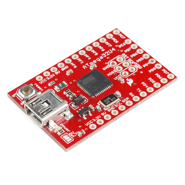
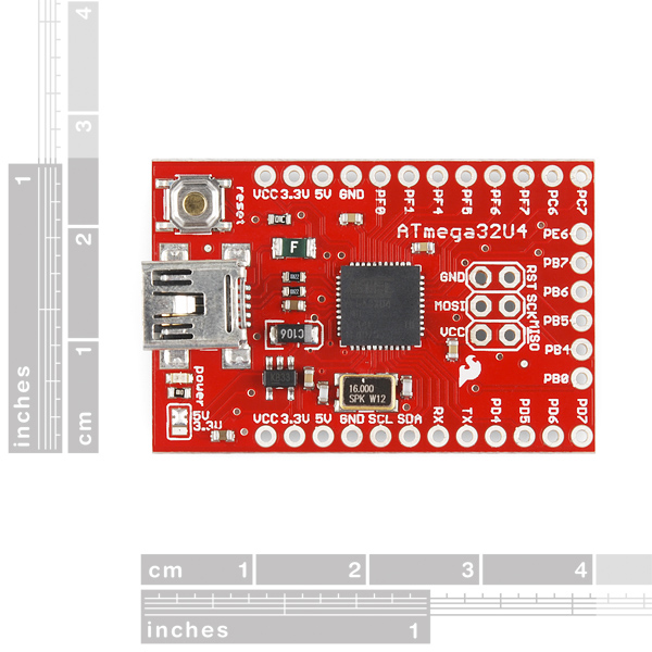
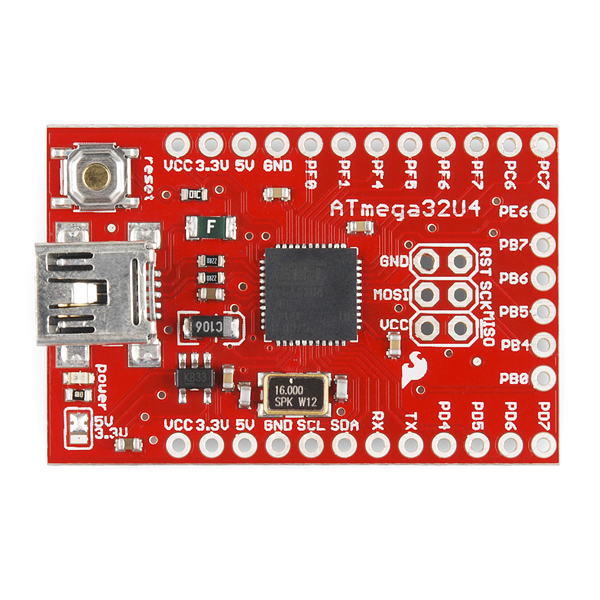
- SparkFun ATMEGA32U4 Breakout

SparkFun ATMEGA32U4 Breakout
The ATMega 32U4 is an 8-bit AVR microcontroller featuring 32KB self-programming flash program memory, 2.5KB SRAM, 1KB EEPROM and a 12-channel 10-bit A/D-converter. It even has on-chip USB 2.0. You might recognize it from our Pro Micro development boards as well as the Arduino Leonardo.
This breakout is designed for people who are interested in programming outside of the Arduino IDE in order to take advantage of lower-level programming capabilities. The board comes pre-loaded with the LUFA CDC bootloader, which allows you to build your code with WinAVR and then program the chip through the USB interface using the program AVRDUDE and without using an external hardware programmer.
When you power the board on, your application will run by default. If there's no application in program memory then the bootloader will run. If you have an application already on the IC and you want to reprogram, simply press the on-board reset button and the bootloader will run for 7 seconds to allow time for programming.
The first time you plug in your board, Windows will ask for a driver. Install the INF file below and the board should enumerate as a COM port.
Each pin on the breakout board is labeled with the AVR pin name including the port letter (PB0, PF6, etc.) to make prototyping a little easier. This is a great board for anyone who is thinking about making the transition from Arduino to AVR C. Check out the Github repository for updated example code, the bootloader source and build files, and additional programming information.
- Schematic
- Eagle Files
- Datasheet (ATMega 32U4)
- Driver
- Github Page
- LUFA Project
SparkFun ATMEGA32U4 Breakout Product Help and Resources
Core Skill: Soldering
This skill defines how difficult the soldering is on a particular product. It might be a couple simple solder joints, or require special reflow tools.
Skill Level: Rookie - The number of pins increases, and you will have to determine polarity of components and some of the components might be a bit trickier or close together. You might need solder wick or flux.
See all skill levels
Core Skill: Programming
If a board needs code or communicates somehow, you're going to need to know how to program or interface with it. The programming skill is all about communication and code.
Skill Level: Rookie - You will need a better fundamental understand of what code is, and how it works. You will be using beginner-level software and development tools like Arduino. You will be dealing directly with code, but numerous examples and libraries are available. Sensors or shields will communicate with serial or TTL.
See all skill levels
Core Skill: Electrical Prototyping
If it requires power, you need to know how much, what all the pins do, and how to hook it up. You may need to reference datasheets, schematics, and know the ins and outs of electronics.
Skill Level: Rookie - You may be required to know a bit more about the component, such as orientation, or how to hook it up, in addition to power requirements. You will need to understand polarized components.
See all skill levels
Comments
Looking for answers to technical questions?
We welcome your comments and suggestions below. However, if you are looking for solutions to technical questions please see our Technical Assistance page.
Customer Reviews
No reviews yet.
Hi, I checked in the datasheet and saw that you need different configuration of pins VCC AVCC, UCAP and UVCC for 3.3V power supply and 5V power supply (section 21). However, on your board they are the same. Also you have only one quartz oscillator on board (16 MHz) which is not suited for 3.3 volts. Does the device work properly at 3.3V? If yes, how is it possible?
I could be wrong on this, but my interpretation is that section only applies to the USB port, not the rest of the device. If you have this board plugged in over USB it will be running at 5V. If you were getting 3.3V over your USB connection then the USB might not function correctly. But you should always be getting 5V over USB.
As for running this at 3.3V, if you check out figure 29-2 it looks like you can safely run this at 8MHz down to 2.7V.and 16MHz down to about 4.5V. As to unsafely that is another story. We often run the ATMega328 at 3.3V 16MHz with no problem which is out of spec as well. Remember, just because it is out of spec doesn't mean it won't work.
Hmmm, If I plug USB cable in this board I get 5V, so everything's ok with that. But on the board there is a SJ1 jumper that allows to change chip's supply from 5 to 3.3V. If I choose to drive it at 3.3V than the pin configuration on this board is different than what specs recommend. I made a PCB containing Atmega32u4 + some other sensors and followed this schematics, all at 3.3V and didn't get it to work. After switching to 5V, everything was fine. My first assumption was pin configuration fail. Did you have experience with successful 3.3V/16MHz/this pin configuration combo?
I haven't personally tried. I know we also use this IC on the Pro Micro (both 5V/16MHz, and 3.3V/8MHz versions), but I can't think of anything we've actually tried at 3.3V/16MHz.
I can not get a program to run after it is uploaded via the Bootloader. If I upload the new program (BASC AVR developed program) with the Bootloader it will run after the upload, but if I power it down then the program will not run it looks like it is looking for the bootloader. Paul
I have the same issue. When I upload a new program using Avrdude ( -c Avr109) it recognizes LUFACDC and indicates a successful upload. A led on B0 will start blinking as programmed but if I disconnect power or hit the reset button the program is lost. I assumed the program would stay until reprogrammed.
i got same issue, does anyone know howto keep the program persist?
Or you could have just resold Ladyada's 32u4 breakout: https://www.adafruit.com/products/296 And that version has all the pins available to breadboard with. This is a nice board, but why would you pay $5 more ($9 more than Teensy) for a red circuit board?
I am not connected to Ladyada (or PJRC) in any way. I just believe in getting the most bang for you buck.
EDIT: Sparkfun lowered the price to match.
I don't know about 10 hours ago, but as of the posting of this reply, there isn't really price difference between Ladyada's 32u4 breakout board and Sparkfun's (Ladyada's price is $20.00 even). As far as the shape of the board, it's largely depends how it's going to be used. Ladyada's is definately easier to use in a breadboard, but in a more finished device the Sparkfun layout could be a more efficient use of space. However, both boards are suitable for both proto-typing and use in a final design, so it's really a personal judgement call.
I'm statisified customer of both Adafruit and Sparkfun and have been for a while. I think they are both great companies and the differences they sometimes have in their design practices and what they choose to sell ultimately benefit their customers by giving them more options.
From the link you posted, it looks like the Adafruit 32U4 breakout is $20. It also looks like the Teensy is $20. If you've got a place where you can buy the Teensy for $11, please post a link so I can shop there.
Yeah, they dropped the price from $25 where it was. Thanks Sparkfun!
The Teensy can be purchased directly from PJRC for $16.
This was listed for $25 yesterday, so I think DML-P was talking in reference to this costing $25.
Hi, I recently purchased this board,when I run the sketch from arduino the program works well,but if i restart the power or reconnect the usb cable,it aromatically goes to bootloader mode,I pressed the reset button but nothing happened :( can someone help me ? thanks
I learned that Sparkfun tied the bootloader pin to ground. This means that the board will always go into bootloader mode. So if you have any bootloader (or none) other than the one they provide, the chip is useless. In order to fix the problem, I cut the copper pour between the HWB pin and GND. I then put a jumper in between HWB and GND so that I can choose whether I want the chip to go into bootloader or not. http://imgur.com/mqOOHmR
I was bummed to find that out with the board. Once I fixed it, I was able to download whatever bootloader/program code I wanted. I could use FLIP to download LUFA code and verify that it runs.
Email us at techsupport@sparkfun.com and let us know more about how you uploaded code and exactly what you are seeing. There are quite a few reasons this isn't working.
VirtualSerial.c:66: error: unknown field 'DataINEndpointNumber'. LUFA-130303.zip's LUFA directory is copied to the LUFA directory, but I can't find that field in the USB.h file. Any suggestions will be appreciated. Thank you
You have to use LUFA 120219. We just fixed that problem.
I can't access the page for the old version (DEV-10277). All attempts just redirect me here. I need the driver software for the earlier version to make my old ATMEGA8U2 breakout work.
Sorry about the delay, we've updated our site to always point you to the latest version, the links of retired pages have consequently changed their addresses a bit. The easiest way is probably to go to the previous versions link on the right of the page. If you have any other questions feel free to email techsupport@sparkfun.com
Definitely be wary of this board under Linux.
The LUFA bootloader version that is shipped DOES NOT WORK with many recent Linux Kernel USB drivers - in particular Ubuntu 12.04 LTS! Please Sparkfun, update the firmware - a fix has been available in the LUFA repos since August 2012...
Instead of being away merrily developing on my Linux setup, I'm having to look at getting an ISP setup and for the time being running under Windoze. This sucks.
Otherwise, though, the board was the best option in terms of hardware features and price for me for my project, so I'm bummed out that the support is not upto scratch.
JFYI, If you're trying to use it on linux and it fails with "Input/Output" error when trying to talk to the bootloader : https://groups.google.com/d/topic/lufa-support/kKuFY8HGgWc/discussion
In short: LUFA has a bug ... So you need to take the SVN version, apply the patch (if not merged in the mean time), compile it (need to mod the makefile for the board) and then flash it using the ISP header and an external programmer.
Ack, this is really frustrating. I see the same issue with some boards purchased just a few weeks ago, and it looks like the github repo with the bootloader hasn't been updated since initial release. Moreover, the github repo doesn't even compile against the current SVN checkout of LUFA.
Linux users should probably stick to the Adafruit breakout for now; their bootloader seems to be a little more solid.
what info do you have on the fuse that is used on the vbus? i cant find it anywhere
Hi, I'm absolutely new to this. Could anyone, please, give me some links about any sort of quickstart guide or startup project like led blinking?
I'm sorry for my newbie questions, but thanks in advance for your help.
Pushing the reset button to reprogram is a bummer. What I like about the old Arduino Pro was the use of the extra serial line to pull down reset. This means I could tweak my code, compile, upload and re-start the AVR without ever having to touch my physical setup, ie. "make all" fire and forget reprogramming. Particularly useful when the AVR is buried in some physical enclosure.
Is there some way to add something to my project code, tweak the USB on the AVR, or modify avrdude somehow to give me back fire and forget reprogramming?
Honestly, that's the functionality I wanted when I originally designed this board and was modifying the LUFA bootloader. Since I wasn't able to solve this problem in a reasonable amount of time, I decided the reset button was the best option for getting into the bootloader.
Currently, the board always boot's into the user's application on power-up, unless the reset is hit. I liked this better than the alternative of using a switch on the HWB pin. With the switch, you would have to touch the board twice as often. Once to default into the bootloader for programming, and once again so it loads the user application.
If I can figure out how to do it so no physical reset is required, I'll modify the bootloader and/or hardware to make sure it happens. I definitely understand not wanting to hit the button every time, especially if you're already using an enclosure.
Assuming one can jump to the bootloader at anypoint in user code, feels like you should be able to usurp one of the AVR USB reset interrupts to jump to bootloader. ... and figure out how to trigger the interrupt from a modified avrdude. I'll first have to buy this avr. :)
Haha, well I'd definitely give you mad cred if you figured it out!
Regardless, I'll be looking into it more and see what I can do.
This is how the Arduino team does it: https://github.com/arduino/Arduino/blob/master/hardware/arduino/cores/arduino/CDC.cpp#L109
If a serial connections at 1200 baud makes a connection and closes it, it will reset using the watchdog timer. See the following page: http://arduino.cc/en/Guide/ArduinoLeonardo#toc12
I also just found a bug in the Leonardo bootloader, as the power-on reset detection didn't work properly. See my pull request for more information: https://github.com/arduino/Arduino/pull/93
After that the board works perfectly, it automatically reset when you are trying to upload to the board and skips the bootloader if the reset button hasn't been pressed!
You might try just to upload the updated .hex file from my fork: https://github.com/Lauszus/Arduino/blob/master/hardware/arduino/bootloaders/caterina/Caterina-Leonardo.hex and I think it will work just as perfect on your board.
Hope that will help your further development!
Great work! I'll be testing this out soon.
A note for noobs: Right click on the link and 'Save link as' will only get you the webpage - not the actual hex. Instead, go to the page, click the 'Raw' tab, and save that page ;) Btw - thanks Lauszus! Works like a charm.
Worked for me! Just had a small power issue that was my fault. Great work!
Excellent! Simple hack and doesn't require a modified avrdude. Look forward to giving it a try when I get one of these boards.
In Windows 8.1 I get an error when attempting to install INF. It complains that "The third-party INF does not contain digital signature information". Any suggestions? Joel
Sounds like you need to disable device driver signing. Check out this tutorial to find out how.
I started with the USB AVR, I made my own PCB with the 32u4. I'm using the FDU Bootloader, Does someone know the clock that this use by default? In my PCB design I can change the crystal, I'm using 16 MHz crystal, and the times, for example with delays don't match. Reading datasheet I understood that by default it have the internal oscillator and the clock division, but if retreat the Crystal my blink code stop. I'm a little lost. Hope someone can help.
If you're programming using the Arduino IDE, check that your board selection has the same crystal frequency as your homemade board. There's a frequency variable in the board definition file that the compiler uses to select the right dividers for baud rate, etc. If that doesn't match the actual crystal, the timing won't be right.
I would suggest ordering the voltage selection pins 5V, Vcc, 3.3V (instead of Vcc, 5V, 3.3V) so we can breadboard a switch in without wires.
To flash a hex file onto the board, you need to have this board's driver installed and avrdude. Then by downloading the example code from GitHub, you need to type make program in the command prompt in order compile and flash the .hex file to the board. Make sure that you have modified the Makefile to set the COM port that the Atmega32u4 has enumerated to as shown in your device manager.
I have a digital sensor that generates one bit data with 1MHz frequency, I want to send this data to a file in my PC. The problem is that the writing speed is so low that I loose the sensor's data while writing. Please let me know if you have any idea about fast data transfer with this mic.
Hi, I am not used to use these type of mics. I have a question. Does the micro-controller have an internal clock? What is its frequency? I need to connect a microphone to this board which needs 1MHz clock frequency. Can I provide it by the micro-controller or should I just buy an oscillator?
The board is set up to use the external 16MHz oscillator by default. You could use a timer to get a 1MHz output. Alternatively you could configure the device with its fuse bits to use the Internal RC oscillator (8.0MHz) with CKDIV8 setting, resulting in 1.0MHz system clock. It just depends what your trying to accomplish.
Why does the microphone need a 1MHz clock? Does it have a built in processor or sophisticated amplification circuit?
Also, I don't see any blinking on my board that shows that it is programmed.
Thanks for your response. The microphone is a digital one and works only with the clock range of 1 to 3 Mhz. I have another problem. I have installed WINAVR and I am trying to use the output program in github page. But it seems that I cannot run the program. I have connected an oscilloscope to port D5 but it does not show that it is set to one or zero. Please let me know if I need to take any steps before just programming the board. I am sure about the com port.
In the next revision of this board, could you please put a jumper at PE/HWB? The current design requires the user to use the CDC Bootloader with the 7-second programming time. Unfortunately, it prevents users from using other (DFU) Bootloaders. If you put a jumper or switch onto PE/HWB, that will provide users to install any bootloader they want and use any atmel programming tools.
What makes you think you can't reprogram the bootloader section and the FUSE bits so that you can use a DFU bootloader?
I don't understand why this didn't come with the DFU bootloader instead of the CDC bootloader. No one wants to remember COM (aka /dev/ttyUSB*} port numbers...
I have the 8u2 version of this board and I'm looking into PDI for the XMega chips. Is there any way to use this to program an XMega over PDI?
I'm trying to use this board with SPI connected to an nRF24L01 for wireless communication into USB, as the receiver for a remote. But SPI is PB0-3. Only PB0 is on this breakout board, and it's on the short edge. What happens to PB1 (SCLK), PB2 (MOSI), and PB3 (MISO)?
PB1,2,3 are not connected to the outer pins, but they can be accessed through the ICSP header.
The LUFA-120219 allows compiling of the virtual serial example. Thanks member #472092 ! Presently, the bootloader always comes up in bootloader mode and only leaves to application mode when the character "E" is sent to it, which occurs after programming, too. (Several post note this behavior.) However, I notice that the bootloader was updated to LUFA-130303 and am wondering if the 7-second functionality in the product description was lost during this update? Is the previous version available? I appreciate the time everyone has put into this project. Thanks
Has anyone else had any problems with false low readings on IO pins? I have the DDRD set properly and am trying to read input PIND7 on PORTD. I am outputting the register over the serial port, it shows that pin 7 is low, but I can read it with a multimeter and it is at 5V. I have also output the DDRD to verify that DDD7 is a low, for input.
Is this a problem coming from the booloader? I have actually been flashing the board over SPI using a MKii programmer. Has anyone else had this issue? Help?!?!
*taps heals together 3 times* I wish for a breadboard friendly version of this, with microUSB (like your Pro Micro), and mounting holes.
Yes this is what I see also. Anyone got a suggestion? Thx, Paul
You are going to have to be more specific. If you have problems with the board feel free to email techsupport@sparkfun.com as well.
The board works, it is just that after I use the USB loader the program does not run after a power cycle. It is acting like it is waiting for the boot loader to finish.
This is a great little breakout board for the Atmega32U4. The only thing it's missing are mounting holes.
Could anyone enlighten me as to why Sparkfun doesn't like using the exposed pads on these things? The Pro Micro doesn't have one either. They must be there for some reason, no? I'm currently designing an Atxmega32u4 board, and it seems even the Atmel datasheet doesn't say anything specific about whether the exposed pad should be connected to anything... weird.
Does anyone know if there's a full-fledged graphical IDE out there which will work with this board? Also, does anyone know if this board can be programmed using the Atmel flip utility? I installed the INF driver for this board, it enumerates as a com port for me (COM5), but Flip doesn't seem to recognize any RS-232 communication, or really provide a way for me to connect to the board.
Thanks.
When programming this over usb,what programmer to I set in my makefile? I've tried avrisp but I get the following error when i try to program it: "avrdude: stk500_getsync(): not in sync: resp=0x3f". I've verified I using the right com port and have the driver installed.
Hey, you probably figured it out. But in case anyone else needs this (I did) its avr109
Hi, i got two of these for my project in school and i'm having trouble with one of those who does not seem to let anything into the flash. I flashed the led blinking example from the githhub page and one board seems to work in charm while other gives out error that looks like this. avrdude: verifying ... avrdude: verification error, first mismatch at byte 0x0000 0x0c != 0x00 avrdude: verification error; content mismatch
avrdude done. Thank you.
did i set any memory lock bits by accident? even though i guess it is not possible to set them in self programming mode. I did the chip erase instruction but it doesn't seem to change the contents in flash. anyone got any solutions?
Does this work with arduino? I want to have an arduino Leonardo compatable for computer lighting. :)
Hi,
I'm using a sparkfun atmega32u4 breakout board. I have it connected to the pc with usb and I've programmed the "virtualserial" program available from here. Both the examples given here worked out fine the first time I've plugged the board in and after that I've programmed it several times. The first time I programmed this, it asked for the driver, and as per given instructions, I installed the provided driver and the mcu (running the program) showed up in pc as a COM port. Problem started when I unplugged the board and plugged it in again later.
When I press the reset button, the bootloader starts okay, and I can program one of the virtualserial example program successfully. But then the user program starts and the board shows up as an unknown usb device in stead of a COM port. In device manager, it says in the device status, "Windows has stopped this device because it has reported problems. (Code 43)". I've tried uninstalling the driver and then reinstalling it, windows won't install it saying it already has an up-to-date driver for "unknown device".
Could you, please, tell me how I can fix this problem at your earliest convenience?
Thank you.
EDIT: I somehow fixed it. I downloaded a new copy of examples and programmed it. I don't know why the old copy was giving me problem. They seem identical, but there must be some unwanted difference I probably introduced by mistake. Thanks, anyway.
The ATmega32U4 shows an internal pull-up resistor on the RESET line (page 50 of the datasheet). Is there some reason I'm missing for an external pull-up resistor on the RESET pin?
is there a special reason you are using a crystal in this and not a resonator? Is the resonator not accurate enough for this micro?
I believe (but don't quote me on this) that a resonator may not have enough precision and/or accuracy for proper USB communication. The USB needs to use a PLL to multiply the frequency up to some multiple of 12 MHz (probably 16 * 3 = 48 / 4 = 12 MHz), and any slight variations will probably only be magnified. If USB was not in use, a resonator would be acceptable for the vast majority of cases.
I just want to Say the Teensy is very cool. real USB instead of that farce they use on the Arduino. All the real USB options like high speed data, Plug n Play, mouse/keyboard emulation etc...
It seems in a way that Arduino is horning in on a superior idea, and renaming it Leanardo.
Viva la Teensy - down with renaming fraudsters.
Thank you Sparkfun making this product. I have been using the Atmega8u2 and they are great. But this is even better! This is amazing work as it looks to be slightly smaller than the 8u2 and has more pins! Good work!
Will this also be offered in a 3.3V 8MHz version or do I just change the solder jumper to 3.3V and run it at 16MHz at 3.3V? If so will the Arduino boot loader have a 3.3V 16MHz option too?
There won't be a different 3.3V version of this board.
If you want 3.3V operation, all you have to do is change the solder jumper to 3.3V. Technically, 16 MHz is out of spec for 3.3V according to the datasheet (you're essentially overclocking). In practice however, it always seems to work just fine.
You also shouldn't need a new Arduino entry. The entry changes because of the frequency, not the voltage. If you are just changing the operating voltage you should be fine.
I can confirm that it will work down to about 2.65v depending on how much bypass capacitance you have. It is also very easy to modify the bootloader and add a a board type to the IDE. Since you guys have your own VID/PID its no problem, but for those creating a new project look into grabbing a PID from Openmoko.
The 32U4 can't run at 16Mhz on 3.3V It needs more voltage.
Oh, guess I should change my 3.3V teensy that I've been using for 3 months back to 5V so it can work.
Running it at 16 or 20MHz and 3.3V is overclocking. That doesn't mean it wont work, it just means that it may not be stable.
Lots of people overclock the 32u4. It's quite stable at room temp. I've seen conjecture that it doesn't have the same temp range at 16mhz/3.3V. My 2 3.3V teensys have been rock steady. I wouldn't ship a product based on it though.
Can the bootloader from the pro micro be loaded on this one? Given that it brings out all the 32u4 i/o pins and costs $5 less, it looks like a better "leonardo" than the pro micro.
Yes, but the pin labels might not be ideal for an arduino.
The Adafruit board is a bit more breadboard friendly since all the pins are on two sides of the board and on .1" multiple centers. Your board would short out pins on a standard breadboard (as would the Teensy). I think the Adafruit board has a different bootloader, but one that is also avrdude compatible. OTHO your board is smaller and will fit into smaller projects. The Teensy is cheaper only if you buy it direct from PJRC, othewise it is also $20. Well, choice is good.
I recently purchased the Teensy and saw that same issue. My solution was to solder the headers for that one row of pins facing up and then using the M/F jumper wires to go where I needed on my breadboard.
Hmmm, maybe this will be in the new product post? 119 in stock, darn somebody got to it before me! oh well