- Home
- Product Categories
- Robotics
- RedBot Kit

RedBot Kit
Replacement: None at this time. We are no longer carrying this RedBot Kit in our catalog, however we are working on a new rev that includes some of the new RedBot parts, check back later for more information. This page is for reference only.
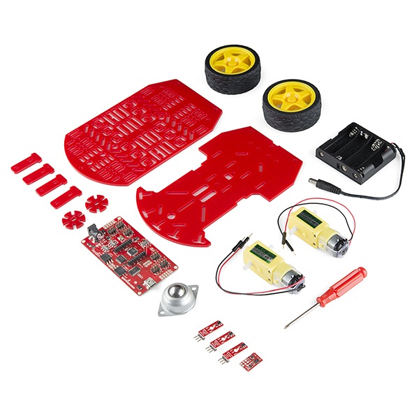
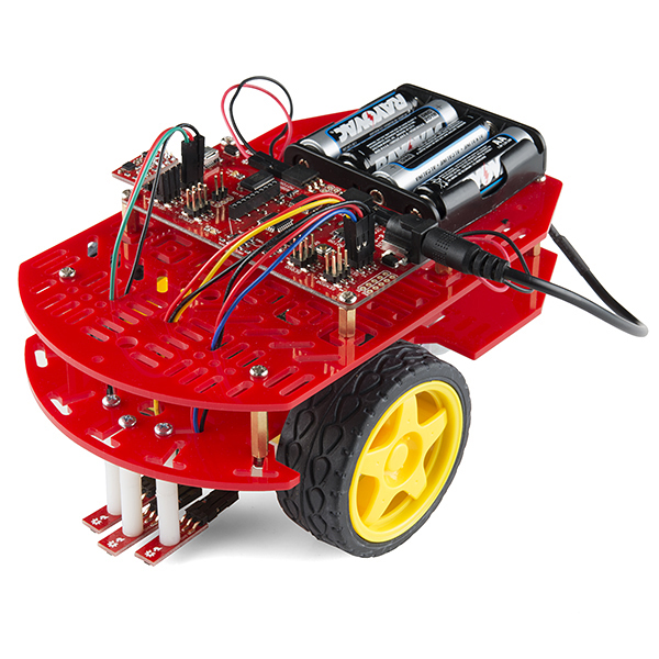
Welcome the RedBot Kit, a robotic development platform capable of teaching two motor robotics and sensor integration! This kit comes with our new RedBot Mainboard, the Magician Chassis, a handful of sensors, and everything required for assembly.
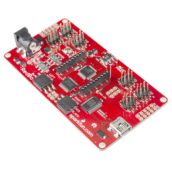
The RedBot Mainboard is a modular robotic development platform that works with the Arduino IDE. The RedBot is a motor driver and Ardiuno combination with various headers and connections, eliminating the need to stack multiple shields to get desired. By simply connecting a USB mini-B cable, you can program it in the Arduino IDE using our example code, or your own.
The Magician Chassis is an economical robot platform with a lot of versatility. It features two gearmotors with 65mm wheels and a caster. The chassis plates are cut from acrylic with a wide variety of mounting holes for sensors, controllers, power, etc. The chassis does require some basic assembly but detailed instructions are included in the RedBot Kit.
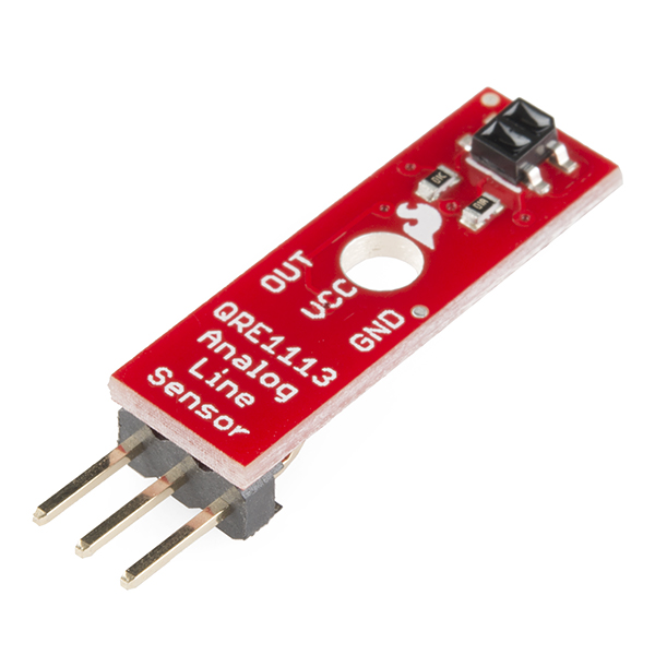
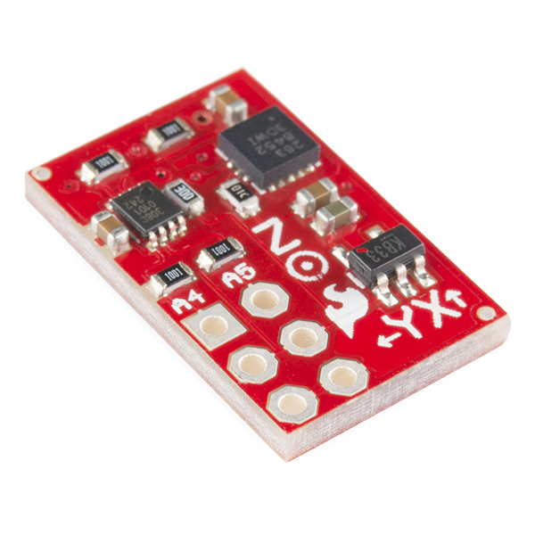
Rounding out the group are three Line Follower Sensors and one Accelerometer Sensor. The Line Follower sensor gives your robot the ability to detect lines or nearby objects using infrared light. The Accelerometer sensor provides bump and motion detection by measuring acceleration forces on the x, y, and z axes.
The RedBot Kit won't be able to operate on Mars but it will definitely fuel your curiosity about robotics!
Note: This kit ships without batteries. You will need 4 AA batteries to get rollin'.
Replaces:ROB-11988
- 1x RedBot Mainboard
- 1x Magician Chassis
- 1x Accelerometer RedBot Sensor
- 3x Line Follower RedBot Sensor
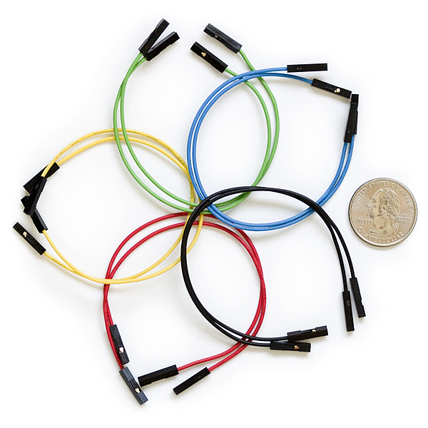
- 10x F/F 6" Jumper Wire
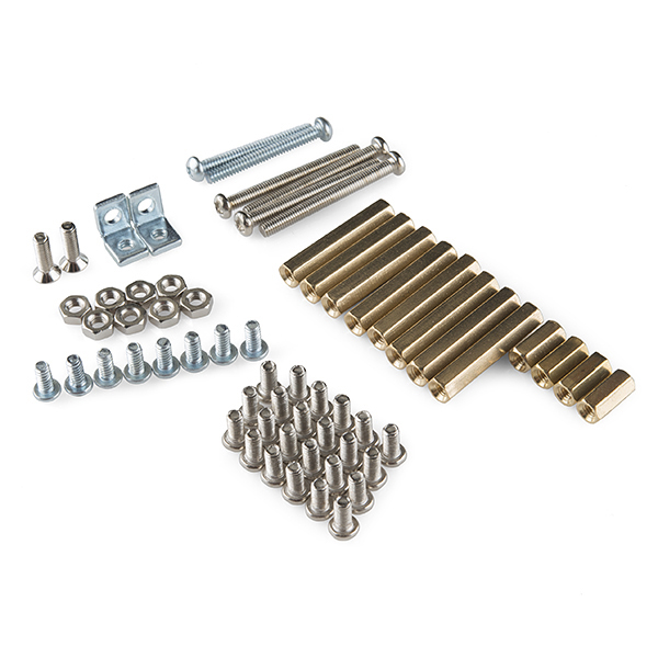
- 2x 4-40 Angle Bracket
- 2x 4-40 1" Phillips Screw
- 8x 4-40 1/4" Phillips Screw
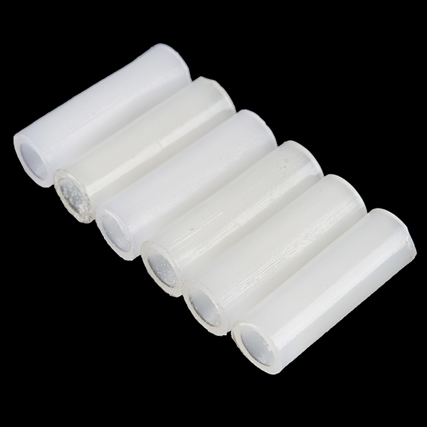
- 6x 4-40 3/4" Nylon Standoff
- Schematic (RedBot)
- [Schematic](http://cdn.sparkfun.com/datasheets/Robotics/RedBot Accelerometer.pdf) (Accelerometer)
- Schematic (Line Follower)
- Eagle Files
- Arduino Library
- Quickstart Guide
- RedBot Assembly Guide
- Magician Chassis Instructions
- GitHub (Design Files & Example Code)
- Wishlist
- Product Video
RedBot Kit Product Help and Resources
Core Skill: Soldering
This skill defines how difficult the soldering is on a particular product. It might be a couple simple solder joints, or require special reflow tools.
Skill Level: Noob - Some basic soldering is required, but it is limited to a just a few pins, basic through-hole soldering, and couple (if any) polarized components. A basic soldering iron is all you should need.
See all skill levels
Core Skill: Robotics
This skill concerns mechanical and robotics knowledge. You may need to know how mechanical parts interact, how motors work, or how to use motor drivers and controllers.
Skill Level: Noob - You will be required to put together a robotics kit. Necessary parts are included and steps will be easy to follow. You also might encounter basic robotics components like bearings, mounts, or other hardware and need a general idea of how it goes together.
See all skill levels
Core Skill: DIY
Whether it's for assembling a kit, hacking an enclosure, or creating your own parts; the DIY skill is all about knowing how to use tools and the techniques associated with them.
Skill Level: Noob - Basic assembly is required. You may need to provide your own basic tools like a screwdriver, hammer or scissors. Power tools or custom parts are not required. Instructions will be included and easy to follow. Sewing may be required, but only with included patterns.
See all skill levels
Core Skill: Programming
If a board needs code or communicates somehow, you're going to need to know how to program or interface with it. The programming skill is all about communication and code.
Skill Level: Rookie - You will need a better fundamental understand of what code is, and how it works. You will be using beginner-level software and development tools like Arduino. You will be dealing directly with code, but numerous examples and libraries are available. Sensors or shields will communicate with serial or TTL.
See all skill levels
Core Skill: Electrical Prototyping
If it requires power, you need to know how much, what all the pins do, and how to hook it up. You may need to reference datasheets, schematics, and know the ins and outs of electronics.
Skill Level: Competent - You will be required to reference a datasheet or schematic to know how to use a component. Your knowledge of a datasheet will only require basic features like power requirements, pinouts, or communications type. Also, you may need a power supply that?s greater than 12V or more than 1A worth of current.
See all skill levels
Comments
Looking for answers to technical questions?
We welcome your comments and suggestions below. However, if you are looking for solutions to technical questions please see our Technical Assistance page.
Customer Reviews
No reviews yet.
Also interested in seeing this kit available again.
Hey I'm also interested in the release of the new kit! I saw the chassis still available on your website, but I'm rather inexperienced and wouldn't necessarily feel comfortable trying to configure the bot.
Any timeline on the new Redbot kit? I have a few boys that are interested in it for a merit badge and this would fit the bill.
Yes, please tell us when this will be available. Really could use one in my school program.
Anyone? Anyone? Buehler?
Is there an ETA yet?
Nothing in the system yet. We're updating a few parts in the kit, so this SKU will be retired and replaced. The new one will likely be mentioned in the Friday new product post when it's made live.
Nope, no announcement today.
Any details?
I want to move the redbot using bluetooth. What do I buy ?
Have used different Arduino before so am familiar with platform. I am getting the same: avrdude: stk500_getsync(): not in sync: resp=0x00, message and can't figure out why. Under ports, I see a valid connection with USB Serial Port(COM3). I cannot download to the board, get above message. Board type is set to Arduino UNO. Speed is 9600. D13 LED is blinking. Tried XBEE Serial set for HW and SW. NO output at serial monitor window. Removed sensors. Same issue. It doesn't act like it is communicating at all. What should the driver file read on COM3? What should the XBEE be set for, don't know what this switch does.
I have this version and I posted a comment to the current versions' comments. I can't seem to get this loading through Arduino. I have it all wired up and put together but the receive light remains on when I start the transfer and never goes off until a reset. Am I using the wrong settings? I'm currently trying settings for the Arduino Mini w/ ATmega328. I appreciate the comment on the last post by SFUptownMaker but I don't think it's the power switch as the board does turn on and off.
Note, when not using the robot be sure to disconnect the power supply. The POWER ON/OFF switch does NOT disconnect all power to the headers, which will result in battery drain.
Will 4 NiMH rechargeable AA batteries work with this kit? All the pictures show alkaline batteries which I know provide closer to 1.5V each versus 1.2V for each rechargeable.
You might want to look into finding a 6V NiMH battery pack. It would be great if SparkFun sold a 5xAA battery holder.
I haven't tried but I suspect they will work-ish. The flat discharge curve of NiMH will allow it to run for awhile; your system voltage will probably be in the 4.7-4.3V range. As the voltage drops, you'll start to see weird behavior as the micro falls below the voltage that will support 16MHz operation.
You may also find that the motors won't have enough torque to get going at low speeds.
Try it and let us know!
Bad timing... when is this robotics kit going to be available again? I have a Boy Scout Merit Badge Fair scheduled for March 15th and this is the robot kit we recommended to our attendees. Now I am getting word from registrants that their orders are on back order 2 to 3 weeks that will make things very difficult for us.
4-40 1/2" screws (3 needed and not included) work well for attaching the nylon standoffs to the chassis. The 1/4" included screws weren't quite long enough. And for some reason I had trouble mounting a motor without some drilling help from my dremel. A hole didn't seem lined up properly, but that might have been my error. Other than that, I'm having fun with this kit.
the instructions that come with the redbot are faulty, and only take you up to a certain point and when you look it up, the instructions online tell you something completely different than the written instructions and make you basically start over plus, it doesn't come with all the parts
The Magician chassis instructions aren't good, which is why we went to such great efforts to make a very good assembly tutorial. The assembly tutorial is for the RedBot SIK, which will be forthcoming; not all the parts from that are included in this kit but can be purchased separately.
I want to hook up a blue tooth radio to this. Where are pins 0 (RX) and 1 (TX)?
PD0/RXD and PD1/TXD are broken out through the XBEE header - the switch at the top of the board will have to be set to "XBEE HW SERIAL", otherwise they connect to the A0 and A1 I/O pins (for use with software serial), which are also broken out to the top-left sensor header (so keep any potential conflicts in mind if you decide to go that route).
Somewhat explanatory image: imgur.com/tac7eD8 (Keep in mind that you would connect your bluetooth board's TXO to the redbot's RXI indicated in that image, and bt RXI to the redbot TXO. The labels are for the redbot board.)
Very cool - thanks! I was hoping I could do that, but I'm still new to hardware / schematics. Have been writing software for 38 years though.
My Mac recognizes an Arduino Uno with no problem, but does not seem to recognize the RedBot board. (no tty usb serial option shows up when it's plugged in). I don't need to install a new driver for this do I? I am using arduino 1.0.5 with OS X 10.8.5. Any ideas on how i can get the board recognized?
i think i solved this by going to http://www.ftdichip.com/Drivers/VCP.htm. i downloaded driver 2.2.18 which seemed to work for max OS X. Now when i select my board as Arduino Uno, serial ports show up, and code transmits. hopefully this problem / solution can be added to the quick start tutorial.
If I power the RedBot Mainboard with 7.4v and run the motors on the magician chassis, will I damage the motors? (The Magician chassis page states a 6v max for the motors.)
I've done it; most of my development work with the libraries for the RedBot used a 7.4V two-cell LiPo pack. I find that the motors run very fast, though--almost too fast to be useful.
Thanks for the quick reply. Ok, I might play around with a 2 cell LiPo pack. I just wanted to make sure I wouldn't damage the motors. Thanks!
Hi all, I found this guide really useful for a quick start: http://lizquilty.com/2013/09/22/redbot-kit-assembly-and-basic-code/
The nylon standoffs are virtually useless. Instead of requiring two nylon standoffs to be joined together to create a 1.5" standoff for a line follower sensor, Sparkfun, can you either swap these with a single 1.5" nylon standoff or a 1.5" metal standoff?
We're looking into it; we're going to see if any of our suppliers can make or sell us 1.5" standoffs.
Thanks!
the upload gets stuck more than 3/4 of the way although I selected arduino uno as a board and the tty usbserial as a serial port. I've tried to find a solution for it online, but no success. I'm using arduino 1.0.5 on a Mac OSX 10.9. The code compiles successfully and even uploads to my other arduino boards, but gets stuck forever when I try to upload any code on the main board. It also doesn't give me an error, so it's hard for me to figure out the problem
This was happening to me too and I finally discovered that I needed to install the FTDI drivers (http://www.ftdichip.com/Drivers/VCP.htm) on my computer. After that, I selected the "Arduino Mini w/ ATmega328" option as the board under the Tools menu and the upload was able to complete.
Thanks Adam, I had also this problem and installing the drivers fixed it.
Note: on OSX, you might need to alt-click on the installer so you can bypass the "developer not certified" warning message.
Definitely contact tech support about this. They'll walk you through some tests and diagnose if you have a bad board, and if so, get you a replacement ASAP.
I decided to try to build a object avoiding robot with this(and a supersonic sensor I had). However, I need just one more angle bracket and nut :( It'd be nice if you somehow indicated "hey, you probably want to pick up 5 or 10 of these while you're at it"
Also, I can second the other calls for a full tutorial for hooking everything up to be the line following robot. Putting the chasis together was one thing, but then figuring out where to put the battery pack and board required a ridiculous amount of trial and error.
And finally, it'd be really nice if you had a program preloaded onto it that was just
motor.drive(255)or some such, so we could easily test if it works without having to get the programming environment runningTaken under advisement. We made the decision to go ahead and launch the product before the documentation was 100% because it's so cool...we're working on finishing documentation (including a new batch of sensors!) now, and we expect that stuff to be live in the next few weeks.
I had trouble getting the sketch to load. I kept getting an error that said,"avrdude: stk500_getsync(): not in sync: resp = 0x00,". I reinstalled the software and choose Arduino MiniATMega3281 and it loaded.
No it doesn't do anything.
The powerlight is on, I switched on the motor and I bumped it but it just sits there. Usb cord was removed. Any help?
Try uploading as an Arduino Uno instead of an Arduino Mini. The Mini uses a different upload speed, so it won't work as one.
Also, note that the motors don't run without power attached to the barrel jack.
The line sensors don’t seem to want to follow the line. When I hooked the sketch up to Serial Monitor and printed out the values rLevel = rSen.read(); lLevel = lSen.read(); cLevel = cSen.read(); I get about 940 when there is no black line and it is just sitting on a white poster board.
When I move the line sensor directly under a black sharpie line or black electrical tape, I about 980. This is true even when very close. If I put my figure over the sensor I get about 300. It seems like the sensor just isn’t giving much feedback when it is on a black line.
Any help would be appreciated.
Two things that jump out at me here- first, on a white surface, you should be getting a lower number. The more light reflected from the surface, the more the transistor conducts, and the closer to 0V the output node will be. When I set up a RedBot, I stack two of the standoffs together, which puts the sensor ~1.5mm off the surface, and gives good results.
Second, you may find that the materials you're using for the line are not as opaque to infrared as one would hope. I've had terrible results with a black Sharpie; it might as well not even be there, no matter how many times I go back over it. Electrical tape has been better to me, but that may vary by manufacturer; I've also had good luck with black acrylic paint (but let it dry before turning the robot on, or you'll end up with weird little ant-tracks from the caster all over your board!)(ask how I know...).
Take another look at it with those two facts in mind and see if that helps.
Is soldering necessary? If so, is it to mount the accelerometer? Will it work with both Windows and OS X? I'm assuming yes with the arduino IDE.
Wondering how middle-school student friendly this might be. Looking at this kit for a class environment. Is there a way to be notified with the updated guide might be complete? Really like this kit.
Thanks!
For initial assembly, no soldering is necessary. However, to get a proper connection between the accelerometer and the redboard, you will want to solder those. It can be programmed in the Arduino IDE, which works on both Windows and OS X. We've designed this kit to be more user/student friendly, and hopefully will have an updated kit with updated instructions out by the end of the year. If you haven't done so already, head over to our Learn site and get in touch with our Education department. They have a lot of great resources for introducing this type of stuff into a classroom setting.
What are the sensors needed to use with the "Speed board holder" on the magician chassis? What's really on my wish list for kits like this is for it to include a decent wheel encoder on the shafts with as many counts as possible per revolution. Wheel encoders are necessary to use odometry or "dead reckoning" to calculate the approximate position and heading of the robot, and widen the kits use in education. I found a nice add-on kit (just do a web search of "wheel encoder kit for robot car" on Ebay) that has a 20-line wheels and photo-interruptor boards, but it looks like it won't fit between the motors of this kit. Can Sparkfun consider offering a robot kit like this one that includes decent wheel encoders?
We're working on it. Encoders for the magician will be along in a few weeks.
Are Encoders still in the works. I'm taking a Coursera class that uses the Magician Chassis and they mention using encoders from Sparkfun.
Yes. We're assembling the kits and preparing the release now. Probably not this Friday, but next (31 Jan)
Magnetic absolute or optical ? The AS51xx etc are so cheap they should come standard these days.
Why is there a limit of 26 per customer if you have a price breakdown for 100+ units? ;)
How close to the floor do you have the line-sensor? Looking at the video it seem to be just a few mm. In my kit is the hex spacers 25mm, the plastic 20mm, that is only 5mm closer. What are you using to make the black line?
I'm having trouble getting the accelerometer board to work. It won't initialize. I suspect the problem is that it's not making good contact with the pins of the header, since it just drops in place. I've tried using two jumpers, one between the two ground pins and one between the two Vcc pins in order to stabilize the board, but that didn't improve the problem. Has anyone else had this problem and, if so, have you come up with a work around?
Doh, I looked at the directions again and at the picture. It looks like you've used a female 2x3 header soldered to the bottom of the accelerometer board to make sure there's a good connection. You really ought to include that part in the kit. Another alternative might be soldering directly to the mainboard header, but I think that's a bit permanent for a bot meant to be experimented with.
I cut two 3 pin sections of a strip of female headers and soldered them to the accel board. That mounts it properly on the mainboard without soldering directly to the board and it seems to work just fine.
I
m rewriting a robot control from an Arduino Motorshield
i cannot find out which pins do direct and PWM for ch A and B
I
ve found out the pins are named 2/4 (CH A) and 7/8 (CH B)I just got this kit today. It would be nice if there were some additional directions included on attaching the red board, line sensors, and acceleration board. I managed to figure them out, but there are some extra parts left over, a couple of angle brackets, nylon extenders, and assorted screws, that always makes me nervous. :) I haven't yet fired it up. I'll leave a comment after I get it running.
We are working on getting a more complete guide together for this kit, as well as info on how you could interface the RedBot with various different sensors. I think it should be available within a month or so (there is going to be a new kit to go along with it), so keep an eye out for that!
FWIW, I had plenty of left over hardware when I assembled mine, and it worked just fine. Best of luck with your project!
It looks like the plastic pieces the go on the inside axles of the motors are meant to be used for encoders. Please include instructions on how to mount encoders that will use those pieces.
I would also like to suggest that you include longer spacers for the line following sensors. On my bot, they are too far from the ground, so the difference between dark and light is less than the individual variation in the sensors. When the sensors are much closer to the floor, they seem to work fine.
That is going to be included.
For anyone dealing with the problem in the mean time, you can mount the top piece of the bot with just three of the hex spacers, and then use the remaining three for the line sensors, to get them a lot closer to the ground.
Here is a video of my 7 year old son demoing this kit. http://youtu.be/7QwW0hohKkM
This is a great demo! Thanks for sharing!
Anybody out there used this kit. Is it fun to show kids the wonders of electronics ? Any reviews or comments?
I'm using it to teach robotics programming to the 10 year-old twins, daughters of a friend of mine.