- Home
- Product Categories
- RF
- SparkFun Transceiver Breakout - nRF24L01+

SparkFun Transceiver Breakout - nRF24L01+
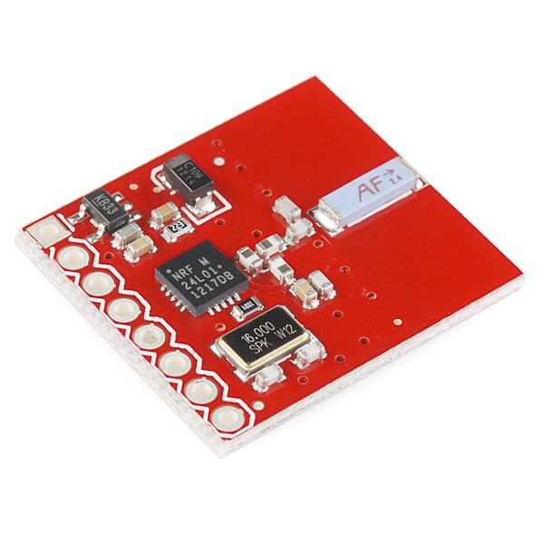
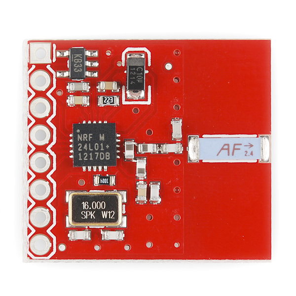
This module uses the newest 2.4GHz transceiver from Nordic Semiconductor, the nRF24L01+. This transceiver IC operates in the 2.4GHz band and has many new features! Take all the coolness of the nRF2401A and add some extra pipelines, buffers, and an auto-retransmit feature - very nice!
Please note: We now populate these boards with the nRF24L01+. The '+' version of the IC has improved range, sensitivity, and data rates. The command set is backward compatible with the original nRF24L01.
- On-board 3.3V LDO Regulator (3.3 to 7V supply allowed)
- On-board ceramic 2.4GHz Antenna
- 250kbps to 2Mbit Data Rate
- Auto Acknowledge
- Auto Re-Transmit
- Multiceiver - 6 Data Pipes
- 32 Byte separate TX and RX FIFOs
- 5V tolerant input pins
- Software selectable channel from 2400MHz to 2525MHz (125 Selectable channels)
- Minimum number of external components
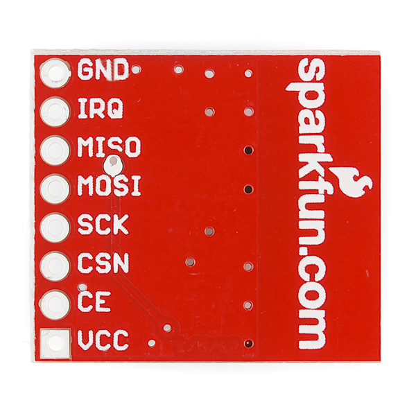
- Pins broken out : VCC, CE, CSN, SCK, MOSI, MISO, IRQ, GND
- Lots of application notes and support on Nordic Semiconductor Website
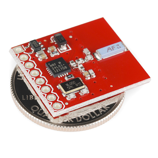
- 0.8x0.9"
SparkFun Transceiver Breakout - nRF24L01+ Product Help and Resources
nRF24L01+ Transceiver Hookup Guide
July 30, 2015
A basic getting started guided to the SparkFun Transceiver Breakout - nRF24L01+
Core Skill: Soldering
This skill defines how difficult the soldering is on a particular product. It might be a couple simple solder joints, or require special reflow tools.
Skill Level: Noob - Some basic soldering is required, but it is limited to a just a few pins, basic through-hole soldering, and couple (if any) polarized components. A basic soldering iron is all you should need.
See all skill levels
Core Skill: Programming
If a board needs code or communicates somehow, you're going to need to know how to program or interface with it. The programming skill is all about communication and code.
Skill Level: Rookie - You will need a better fundamental understand of what code is, and how it works. You will be using beginner-level software and development tools like Arduino. You will be dealing directly with code, but numerous examples and libraries are available. Sensors or shields will communicate with serial or TTL.
See all skill levels
Core Skill: Electrical Prototyping
If it requires power, you need to know how much, what all the pins do, and how to hook it up. You may need to reference datasheets, schematics, and know the ins and outs of electronics.
Skill Level: Rookie - You may be required to know a bit more about the component, such as orientation, or how to hook it up, in addition to power requirements. You will need to understand polarized components.
See all skill levels
Comments
Looking for answers to technical questions?
We welcome your comments and suggestions below. However, if you are looking for solutions to technical questions please see our Technical Assistance page.
Customer Reviews
4.2 out of 5
Based on 5 ratings:
Works great
I got this to test out wtih my WL Toys quadcopter transmitter and it works perfectly! Told me everything I wanted to know. Should be a perfect robotics receiver. BTW, that WL Toys transmitter is a real bargain with lots of channels
Works like a champ!
Very nice transceiver with more features than I'll need. The data sheet is very good and the tutorial filled in some holes. Just now got it talking to a couple of PIC controllers and testing the range, no real experience with RF, so we'll see how it goes.
nRF24L01+ Board
The jury is still out! I have been trying to enable two (2) nRF24L01+ devices (yours included, now) to provide implementation of the NORDIC feature called "Dynamic Payload Length". Sofar, I have been unsuccessful in achieving this goal. I am writing my code in assembly language for a PIC MCU, which should not mean anything other than the fact that I am not using "C"! It is absurd to think that this is impossible, so, I will fight ON! (Any suggestions would be appreciated - other than contacting NORDIC [done this] or finding something on the internet) Jack Doyle, Monitor Engineering
Works like a charm
works great
Why is there a custom oscillator?
Would be nice if these blogs had dates on them. It states it's 'the newest' and I have to look to the comments to see it's 7 years old.
Another comment : because of the regulator, it is not feasible to achieve the low power consumption the nRF24L01+ is capable of. In power down mode, the nRF24L01+ consumes less than 1uA. However the regulator draws at least about 80uA. I measured a total of 90uA in power down mode in one of the modules I bought.
I copied the layout of the RF section for my own board from this one, but I can't get the radio to work when I run an identical configuration otherwise.
Can someone at Sparkfun please confirm that the values in the schematic are accurate to the shipping parts, and would you consider publishing the Eagle PCB files as well?
Please post eagle files
Eagle files posted.
The two links still go to the same PDF...
The link to the Eagle files goes to the same PDF as the link to the schematic file.
where is the eagle file *.brd?... :(
In the link to the eagle files you have a .pdf schematic, could you post the eagle files?
Apart from the regulator and capacitor, this is the reference design found in the nRF24L01 datasheet.
What's the P/N for the SMT antenna?
is it possible too control more then two servos via nRF24L01+ and arduino
Price is somewhat disappointing; Seeed sells a similar, though smaller, module for a (granted, incredible) price of USD 2.90
If you want to learn how to create your own home automation solution based on NRF24L01+. Please visit http://www.mysensors.org
Our Arduino libraries can be found here: https://github.com/mysensors/Arduino/tree/master/libraries/MySensors
Henrik
What does MiRF stand for?
3.3V LDO Regulator means I can control this 3.3 V logic board with my 5V logic Uno correct?
mixing nRF24L01+ and nRF24L01
Hi, I have a TX board with dspic 33FJ and this nRF24L01+ (WRL-00691) and 2 RX board based on DSPF240, one with nRF24L01+ and the other with nRF24L01 when using the RX nRF24L01+ it works well but if I use the RX with the nRF24L01, I got some glitches from time to time and for certain values, it seems that the bytes are not fully received (MSB are not all decoded ???)
Has anybody worked with mixing nRF24L01+ and nRF24L01 ? both are Sparkfun boards.
here are my config
the TXconfig :
while sending :
On the other hand in the RX board (it is a TMS 320F240 DSP) : configure RX
reading, within an interrupt service routine
thanks for your kind help
I've got this kind of module working with PSOC 4. I think it's compatible with PSOC 5. If anyone is interested, please contact me by e-mail ( super_nan at hotmail dot com )
You can get this for $2.75 elsewhere.
On-board 3.3V LDO Regulator (3.3 to 7V supply allowed)... This information is correct?
These seem quite overpriced. You can find a set of two for a little more than $5 if you look hard enough.
Where can you find these for the price you have quoted ?
www.seeedstudio.com. USD 2.90 for 1
Has anyone interfaced this with a PSoC5 ?.. No matter what command I send trough the SPI the return from nRF24L01 is always: 0b00001110 - the status register! It is like the transceiver doesn't receive or understand my commands? Any suggestions? I am kinda desperate :(
The unit responds with same number of bytes you send. Send two bytes - one the command, another dummy. Read two bytes - the first one will be status register the second one is the value of required register byte. BTW SPI mode is CPHA=0, CPOL= 0.
Did you manage to get it to work with PSoC 5 ?
also interested in this ... this module does not have a lot of documentation from what I have found. at least not in the way of easy to follow examples without using pre-existing libraries like for Arduino.
What is the power consumption of this module in PowerDown mode? Some people is mentioning here 80-90 uA, but I am measuring 800-900uA. Sparkfun, do you have an official figure? I am using Mirf.powerDown for that.
i was thinking about shortingn out the regulator, but then i realized that 90uA in standby are not much. The schematics are pretty.
Which library are you using with this module? I am getting 10x more consumption using Mirf.powerDown(). Any idea what could be going wrong?
The Eagle files are not Eagle files, just Gerbers and Drills
Hi I am not an engineer & I just bought this. Can any kind person teach me which pins to connect in order to transmit a bluetooth signal? (eg: VCC and GND to voltage supply) Thank you!
What does backword compatible mean? whats the difference in using the nrf24l01 instead of the nrf24l01+?
in need of assistance.
just got my order today. I have tried talking to it over SPI, but I am not getting any data back. I send a read register command, and the only data coming back is 0x0F during the same period as when I sent the command. No matter what command I sent, the result is always 0x0F.
Am I missing a step? Was there something I need to do before I can talk to it?
Sorry, please ignore that message. One of the settings in my SPI controller was wrong.
I would like to use this part on a robot and the other transceiver would be connected to a PC using USB/serial communication. What are my options on the PC end ? Thanks !
Mine came in red. :)
Anyone who tried to download the Eagle files from here will have noticed that they are the gerbers, not the BRD/SCH files. If the awesome Sparkfun dudes/dudettes could upload the eagle files, that would be appreciated by lots of people I'm sure :)
In the meantime, a good example in Eagle format can be found on this product: http://www.sparkfun.com/products/8602
The benefit of this one is that it also shows the NRF being wired up to an MCU, which I presume most people wanting to skip the breakout would be interested in.
Thanks for the link.
I'm afraid I ran into the same problem as well. All gerbers, no BRD/SCH files...
Range on these is nowhere near 100m. With software-selected output power at a maximum the range i get is about 20-30 meters LOS and 10-15 though a wooden door. I wonder if the version with the antenna would perform better, or if I am just SOL for 100-150m LOS range with these?
That range sounds about right if you're using two of these to communicate with each other. These will transmit 100m but you will need the external antenna version to receive the small signal at that distance. This large antenna works really well.
Is an "nRF24L01+" used on this board or the old "nRF24L01" IC?
In the picture it is the old "nRF24L01" and datasheet link is the same!
Thanks.
where can I find the model Fritzing of this module(Transceiver nRF24L01)?
http://img843.imageshack.us/img843/7985/nrfcircuit.jpg
I'm still awaiting a reply from techsupport.
can anyone confirm the 3.3V regulator is functioning on their board? Mine seems to be producing 5V when supplied with 5V. I was probing the 10uF cap and the via near pin 7 on the nRF24L01+. both read 5V.
Please contact techsupport@sparkfun.com, they can help you with technical questions.
Anyone know if its possible to have this talk to Bluetooth devices as they use the same 2.4ghz band?
even if this means an arduino to process the data
I don't think so.
the 2.4ghz band is used many thing, like wi-fi and microwaves.
Nordic Semiconductor are working on something called ?Blue.
Could I use this with the "Nordic Serial Interface Board" (sku: WRL-09019) and expect it to work?
Yep, WRL-09019 is designed for interfacing with the nRF23L01 via a virtual com port over USB.
What is the gain of the ceramic antenna on these boards? I'm trying to decide between these and the RP-SMA version. Thanks,
the pic code is for what "original" compiler? as mentioned that it can also compile with ccx5. so what was the original compiler used?
Next board revision, it would be nice to run this off 3V, in other words bypass the Vreg.
Grumble: it would be nice to have the 'RAW' net exposed so that you could connect this directly to a 3.3V microcontroller (like the arduino mini) bypassing the voltage regulator. It looks like there are 3 vias on the RAW net, though, so hopefully I can find some thin wire. Can I suggest that one of those vias be enlarged to standard "pin" size for a non-sketchy way to access RAW Vcc?
Note:
The Datasheet link doesn't go directly to the pdf file.
regards
Does anyone have any example code for arduino?
I got this working with the Mirf library (http://www.arduino.cc/playground/InterfacingWithHardware/Nrf24L01) on an Arduino Mini Pro 328.
The range is disappointing however, I only managed 17 feet line of sight indoors, much less with a wall in between. There may be lots of interferences from WiFi access points etc, all using the same frequency.
How much current does this thing consume when on and transmitting?
So an onboard Regulator. That me that I can plug 5v into the VCC?
Can You guys post a schematic? It would be a great Help. Thanks.
Sorry it took so long. Posted now.