- Home
- Product Categories
- Battery
- SparkFun LiPoly Fast Charger - 5V Input

SparkFun LiPoly Fast Charger - 5V Input
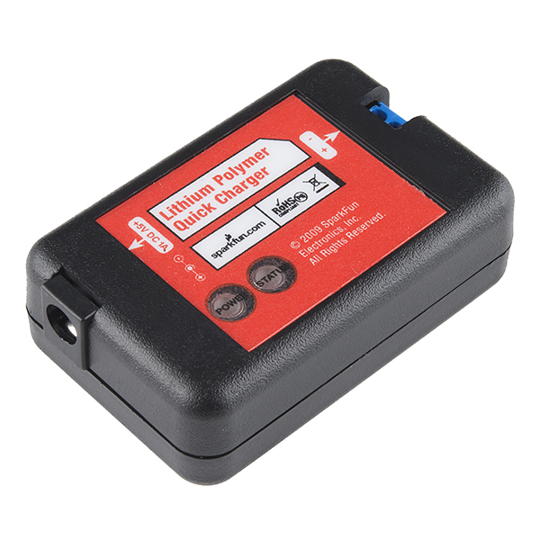
A SparkFun original Lithium Polymer charger. This little black box charges single cell lithium polymer batteries with a max rate of 1A. The charge output is via a 2-pin screw terminal. Top pin is ground, bottom pin is charge pin. Based on the popular Microchip part MCP73843-410.
Note: This charger requires a 5V 1A power supply but does NOT include one with the order. A power supply will need to be purchased separately.
SparkFun LiPoly Fast Charger - 5V Input Product Help and Resources
Core Skill: DIY
Whether it's for assembling a kit, hacking an enclosure, or creating your own parts; the DIY skill is all about knowing how to use tools and the techniques associated with them.
Skill Level: Noob - Basic assembly is required. You may need to provide your own basic tools like a screwdriver, hammer or scissors. Power tools or custom parts are not required. Instructions will be included and easy to follow. Sewing may be required, but only with included patterns.
See all skill levels
Core Skill: Electrical Prototyping
If it requires power, you need to know how much, what all the pins do, and how to hook it up. You may need to reference datasheets, schematics, and know the ins and outs of electronics.
Skill Level: Rookie - You may be required to know a bit more about the component, such as orientation, or how to hook it up, in addition to power requirements. You will need to understand polarized components.
See all skill levels
Comments
Looking for answers to technical questions?
We welcome your comments and suggestions below. However, if you are looking for solutions to technical questions please see our Technical Assistance page.
Customer Reviews
No reviews yet.
-------------------- Tech Support Tips/Troubleshooting/Common Issues --------------------
Green Status LED
Looking at Table 5-1 in the MCP73843 datasheet [ https://www.sparkfun.com/datasheets/Prototyping/MCP73843.pdf ] with the schematic [ https://www.sparkfun.com/datasheets/Prototyping/Batteries/LiPo-Fast-Charger-v12.pdf ], the green status LED should turn "ON" only if it is in the preconditioning state or charging the battery. Once the battery is fully charged, the status LED should turn OFF. This is assuming that you are using LiPo battery that is nominal 3.7V. To safely charge a LiPo battery, the capacity should be above 1A.
There are times when the LED might flicker. That might happen when the battery drops below the threshold voltage and the charger IC turns on again. Or when there is no battery connected.
This is similar to our other LiPo charger [ https://learn.sparkfun.com/tutorials/lipo-usb-charger-hookup-guide#inputs-and-outputs ] . The board uses the a similar LiPo charge management IC (MCP73842) but it is set to a different charge rate.
Is is possible to charge while using the battery or modify it to? I want to use this with the 6Ah LiPo battery and possible connect a solar panel to charge during the day as much as possible.<br />
Great charger, the board is only slightly larger than the other LiPo 7v one. It says up to 12 volt input, but at 10-12 volts this thing started smoking so I wouldn't recommend going over 5v.
Try looking at the datasheet of the part that is clearly given
So does this auto-stop charging once the battery's full? If not, can someone link me to a schematic/part that does?
It slows it to a trickle once it is full.
You can't trickle charge LiPos.
The MCP73843-410 charges to 4.1V and shuts off (not trickling).
It will come back on if the cell voltage drops below 3.9V
I have seen two problems with this. First, if you leave it connected to the battery while the power supply is disconnected current flows through the body diode of the pass transistor and lights the power LED. This drains the battery and makes the power LED useless. I solved this by removing the power LED, but a shottky diode in front of the current sense resistor would be a better solution. This would also keep the battery from discharging if the input is shorted.
The second problem is the timer. There is a 1.5 hour fast charge safety timer controlled by C1, a 100 nF capacitor. This means you can't use it on a large pack like the 6 Ah. You just have to replace that capacitor with the value you like -- the timer is proportional to the capacitance. The ideal situation would be to add a footprint to the board so the user can add a second capacitor in parallel to set the charge time. There is plenty of empty space on the PCB, so it should be no problem to add both a through-hole and a SMT capacitor slot.
This time limit concerns me too, since I'll be charging 400mAH and higher battery capacities, needing a minimum of 3.5 hours at 1000mA charge current. If I'm reading your posting correctly, does the status light indicate charged after 1.5 hours regardless of state of battery? If so, then please give an equation that I can calculate either a replacement capacitor or a second capacitor in parallel. Thank you, Barry
Just to confirm what others stated: > 7V will fry this charger. I killed mine at 9V.<br />
<br />
LED Status:<br />
Charge Cycle State Green LED<br />
-----------------------------------<br />
Qualification: OFF<br />
Preconditioning: ON<br />
Constant-Current Fast Charge: ON<br />
Constant-Voltage: ON<br />
Charge Complete: OFF<br />
Safety Timer Fault: Flashing (1 Hz, 50% duty cycle)<br />
Cell Temperature Invalid: Flashing (1 Hz, 50% duty cycle)<br />
Disabled - Sleep mode: OFF<br />
Battery Disconnected: OFF
Just blew one up myself as soon as I got it, wish I had read the comments. why oh why doesn't sparkfun correct this in the title, I don't think less people would buy it if it was 5v-7.5v dc instead of 5v-12v.!!!!!!!!!
5V really is required, even though the datasheet for MCP73843 says supply 5-12V.
When I connected it to a 5V unregulated wall wart (measures 8.5V with no load), this unit did pull the supply down to 5.1V, but it never charged battery nor turned on the status LED as described in the datasheet.
Changed out for regulated 5V and now it charges like a charm.
yup I can confirm this: even with a 9V input (correct polarity, of course :) the unit gets kinda toasty and started emitting evil smells. Stick with 5V!!
3 words: Power Supply Ripple.
Maybe your wall wart was outer positive?
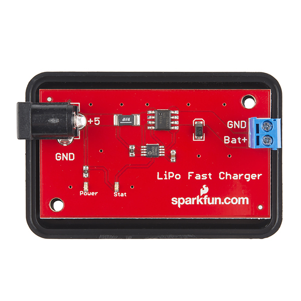
Page 16 of the data sheet gives a formula which implies that a 110 mohm resistor will give a 1000 mA charge current. Your schematic shows two 110 mohm resistors in parallel which gives an equivalent of 55 mohms. According to the data sheet this would give a fast charge current of 2000 mA... way too much. Maybe the photo is right and there is only one 110 mohm resistor after all (???)
This charger will work on Li Ion batteries but will under charge them by about 10%. These want to be charged to 4.2V versus 4.1V for Li Polymer.
Does anyone know if a load can be attached in parallel with the battery? The datasheet of the charge ic does not say anything about this.
In 2008 I bought one of these. Yesterday I used it to revive a dying Acer Iconia A1. I knew it would be useful one day!
Reading through the comments here, the datasheet, and the schematic, I think I have found a few issues:
The datasheet recommends using a reverse-bias protection diode to prevent the battery from discharging into the outlet if plugged in backwards: "The optional reverse-blocking protection diode, depicted in Figure 6-1, provides protection from a faulted or shorted input, or from a reversed-polarity input source. Without the protection diode, a faulted or shorted input would discharge the battery pack through the body diode of the external pass transistor."
This may have been the cause of some smoking and flames.
Also, while the chip itself can handle an input voltage of 4.5 to 12 volts: "4.5 – 12 V"
The power indicator LED setup (LED red in the schematic) does not allow for usage above about 10.75 volts.
I assumed they either used an indicator LED that was 2.0V@20mA or 2.5V@25mA. Using their 330 ohm resistor. I calculated that the LEDs would be hitting their 20 or 25mA limit at 8.6 and 10.75 volts respectively, but would be safely below that when given 5 volts. I derived this from the equation that:
V(supply) = V(LED) + I(LED)*R where R = 330 ohms
When given 12 volts, the current across the LED would be: for 2.0V@20mA 12 = 2 + I(LED)*330 I(LED) = 30mA enough to potentially damage the LED
or for 2.5V@25mA 12 = 2.5 + I(LED)*330 I(LED) = 29mA again potentially enough to damage the circuit.
While this might not cause smoking or flames, the power going through the LED resistor would be approaching 1/4 Watt which would definitely be bad for a 1/4 rated resistor after a few hours.
P = I(LED)^2*R
P = .028^2330 = .259 watts or P = .03^2330 = .297 watts
The LED resistors are the likely cause of any flames.
Another issue is the R(sense) resistor. In the schematic it shows 2 .110 ohm resistors in parallel for a total of .055 ohms which according to the datasheet would put out approximately 2 amps instead of 1. Fortunately, pictures of the actual circuit show only one resistor, so it is likely that this was a simple mistake.
The datasheet calls for the drive transistor and current management chip to be placed as close as possible to the battery outlet for proper voltage regulation. I think that Sparkfun could have moved it over an inch to get better results.
Finally, everyone should take note that this is designed for Lithium Polymer batteries which take a final charge of 4.1 volts as opposed to the standard 4.2 for Li-Ion. This means that if you attached a Li-Ion, you would get about 87% of a full charge according to table 2 on this page made by battery university: http://batteryuniversity.com/learn/article/charging_lithium_ion_batteries
Overall, if you are looking for a complete Li-Ion solution without worrying about input voltage and bias. Make your own charger on the cheap by following the datasheet for the chip and using a reverse-bias diode, a transistor with a higher wattage rating, and LEDs and caps to match your voltage and capacity specs. The major parts are all about 50 cents each and OSHPark will make you 3 copies of a board for $5 per square inch. You also don't have to pay for a pretty piece of injection molded plastic.
Great resource and good circuit, but the devil is in the details.
Does any body know if you can leave the battery plugged in to the circuit, and brach of to my arduino to power it, and whenever i need to charge the battery just plug it in to charge it?
Hi Sparkfun,
Can I use this charger to charge the batteries which are on connected to the circuit. I have 4 CR123A rechargable batteries connected to my circuit.
Else should I use any other protection circuit before connecting this to the battery..??
Thanks,
Very important: Most CR123A batteries are not rechargeable. Make absolutely sure that you're only connecting this battery to a rechargeable single-cell (1S, 3.7V) Lithium Polymer battery, with a peak charge voltage of 4.2V. Connecting a non-rechargeable Lithium battery to this charger will likely result in damage to the battery or even a fire.
As many seem to have trouble with this, it is advisable with nay product to read the datasheet of the devices used, as well as check out the schematic. I've used this chip in commercial products, and it does what it says, but like most chargers, there are caveats. The absolute maximum voltage the charger chip can take is 13V, recommended max 12V - however - the charge current is fixed, there is no thermal cut-off as the pass element (MOSFET in this case) is external. So with 12V in, and say, a half dead battery, 3.6V, the voltage across the mosfet is 12-3.6 = 9.4V. With 1A charge, that will have to dissipate 9.4W in heat. Using a 5V supply? 1.4W. There is hardly any heatsink copper on that board so I think, mounted as it is, the FET can take 2W maximum before it dies of heat. Even with extensive copper pour, I don't see it getting past 4 watts. To be fair, sparkfun did recommend a 5v charger, but no mention of battery capacity. The timer capacitor will have to be changed to give a timeout of greater than the maximum time taken to charge a battery of its specific capacity. This is all in the datasheet, but not completely obvious. I would ask sparkfun to look at switching chargers, perhaps with dip-switch options to set charge current for those who wish to charge 1000mAh to 6Ah batteries, and be able to use between 5 and 15V without things somking.
Anyone know what the dimensions of this are? Thanks.
Can you post the eagle files?
What is the threshold voltage for the status LED? What does it mean when the stat LED flashes green? It comes on solid when charging from Sparkfun's recommended 1000mA charger, but blinks green when I use Sparkfun usb to barrel jack adapter cable powered from either a USB jack cellphone charger 650mA wall wart or a computer USB jack. The battery's voltage was 3.6V when I put it on the charger, so its not an issue with the battery already being over a threshold voltage. Overall, seems like a good unit and it does put out the rated 1A charging current. Btw the board could easily be cut down much smaller, and soldered to instead of using the output jack.
During charging the status led frequently starts flashing and charging stops. Only reset is by power off/on.
I see other comments about flashing status led, but no response from Sparkfun.
Does anyone know why the status led flashes????
With no responses had to ‘do it myself’; looks like there’s not much activity on this item.
The flashing status led indicates a fault condition; the most likely cause is a timeout of one of the three timers on the MCP7384xx chip. Based on the 0.1ufd timing capacitor used in this charger, these periods are:
Preconditioning safety timer – 1 hour
Fast charge safety timer – 1.5 hours
Elapsed time termination timer – 3 hours.
The upshot: if your battery is not fully charged in 1.5 hours of fast charge or 3 hours total (preconditioning + fast charge), the charger goes into fault condition (blinking status led) and stops charging.
Some of the messages suggest using this charger for the 6 Ah LiPoly’s, but a fully discharged battery will take several (manual) resets of the charger to fully charge. Sparkfun finesses this point (by not mentioning it), but does list the 6 Ah battery in the Related Products section for the charger, and lists the charger under the battery. There should be a caveat!
Sparkfun,
Does this work with your 9 volt wallwart adapter? The description says its 5-12v, but from the comments, it looks like you shouldn't use anything over 5v. My status light no longer functions and I've only used the spark fun 9v adapter. Could we get some official clarification?
I've personally used it with 9V just fine. YMMV?
I would hope my mileage wouldn't vary. It either is supported or its not any my device is defective.
It should work that way, and in my experience, it does. Your mileage has obviously varied since you don't share the same experience. It could be defective. Does it still charge? You would be best to contact techsupport@sparkfun.com if you think it's defective.
I�m using a fixed 5 volt supply, but the status led keeps flashing. <br /> <br /> <br />
I want to charge a 3.7v 1530mAH li-po battery but my charger�s status LED is always flashing and I don�t know why, I�ve tried several batteries but the status led always flashes. I already read the datasheet but I can�t find the problem, any suggestions?<br /> <br />
For anyone who is curious, this charger takes a center-positive 5.5x2.1 mm connector, which is a size "M" barrel connector at RadioShack (I bought one of those interchangeable tip wall warts)
I?ve one 7.4v 800mah Li-On battery, anyone know if is it possible to use this charger?
It will not work. This only charges single cells.
The red POWER indicator is illuminated even after the 5v power supply is removed. It can only be using power from the charged battery. What is the point of this?
I'm trying to build a solar charger based on this tutorial:
http://www.instructables.com/id/How-to-make-a-solar-iPodiPhone-charger-aka-Might/
The only changes I wanted to make was to use this 5v-12v rated charger with the 2.5W solar cell (rated at about 8V open voltage and 310mA):
http://www.sparkfun.com/commerce/product_info.php?products_id=7840
Question is, will this set up fry this charger unit? (more importantly, if the modified setup will fry anything else, please let me know.)
Single T, could you please help?
I'm using the charger to charge a new 900mAh 3.7V battery. Well when I connect the battery the "status" light doesn't come on. After an hour, I measure the voltage of the battery and it's still at 0.05V. It doesn't seem to work...what could be the problem?
That may have just been the ripple screwing up the chip's sensing. There's no input filter cap.
Is there a similar board to charge 4 AA 2500 mAh NiMH Battery or even 8 AA
At the moment we do not have one available
Can I exchange this for the out-of-stock charger that's used in the iphone charger that you link to on the Max1555 charger page?
Hi,
Please contact returns@sparkfun.com for more information on exchanges, and returns.
Thanks,
Tim
I didn't actually mean exchange it for a physical one, just will it work in the circuit
Can someone comment on how the status light should function?
I am also curious about the possibility of having a load hooked up in parallel with the battery.
The status light is on when the battery is being charged and turns off when it's finished. It is also off if the battery connected is below the proper minimum voltage (pre-charge mode). If you're charging a cell that you know is discharged (possibly too low), just leave it plugged it in and the light should come on once the pre-charge mode completes (perhaps minutes-hours later).
Btw, this can be powered from a USB but won't get the full charger current (1A) due to the USB specs.
Comparing the schematic to the image of the product, I noticed that instead of using 2 0R11 resistors, you used one beefy "Dale" resistor. What's the value of that resistor? About 0R055?
The reason I'm asking is because I'm making a project with limited space and I want to integrate the charger.
Can this charge the 6Ah triple cell? It says single cell Poly, not sure what if anything would happen if I hooked it up to the triple.
Yes, there is a thread in the comments for the 6Ah battery pack saying that this should be fine.
The charger "sees" the battery packs as one pack, since they are in series. However, if they were in parallel, then we'd have to go somewhere else.
I think you mean they are in parallel. If they were in series, you'd have a higher voltage and they wouldn't charge.
Mine smells funny when I plug it in and charge. I'm using a 9V power supply. Normal?
You shuld use a 5V regulated power supply, have a look at http://www.sparkfun.com/commerce/tutorial_info.php?tutorials_id=57
Looking at the schematic, the red power LED is getting the unregulated input voltage through a 330 ohm resistor. Great for 5v supplies, giving 10 mA or thereabouts, not so great for 12v, with 30+ mA.
The chip itself is rated for 4.5v-12v input voltage.
I just killed one by accidentally plugging it into a 9V supply. The cooked component seems to be the MOSFET. Looking at the data sheet for the NDS8434, the maximum rating for gate to source voltage is 8V. The MCP73843 is probably pulling the gate to ground, and thus exceeding this spec for anything more than an 8V supply. Arguably this is partially Microchip's fault, as they use this MOSFET in their example circuit in the MCP73843 datasheet.
Sparkfun, you probably will want to relabel this product as "LiPoly Fast Charger - 5-8V Input".
I wonder if I could provide the 5V from the USB
That would work.
Will this work with more than one battery or is this a charger like the one that works with 3 - 7 volt input? By looking at this I am thinking that it is only for one, but I am just asking to be sure.
Can this be used in parallel or pass thru for small power requirements (e.g. in my car, I want the LiPo providing power when the car is off, but I want it to charge the battery yet still do the ~100ma to the device when it is on.
How large is the circuit board?
Will this work with Lithium Ion batteries as well?
Yes, look on the first page of the datasheet. It will work with Lithium Ion batteries.