Rotary Encoder - 1024 P/R (Quadrature)
COM-11102
Rotary Encoder - 1024 P/R (Quadrature)
SKU: COM-11102
$48.50
In stock
SKU
COM-11102
Product Overview
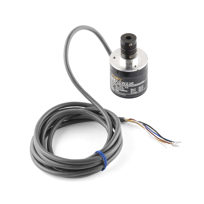
This 1024 pulse per rotation rotary encoder outputs gray code which you can interpret using a microcontroller and find out which direction the shaft is turning and by how much. This allows you to add feedback to motor control systems. Encoders of this kind are often used in balancing robots and dead reckoning navigation but it could also be used as a very precise input knob.
Features:
- Resolution: 1024 Pulse/Rotation
- Input Voltage: 5 - 12VDC
- Maximum Rotating Speed: 6000rpm
- Allowable Radial Load: 5N
- Allowable Axial Load: 3N
- Cable Length: 50cm
- Shaft Diameter: 6mm
Documents:
- Datasheet (A6B2-CWZ3E-1024)
- Example Code
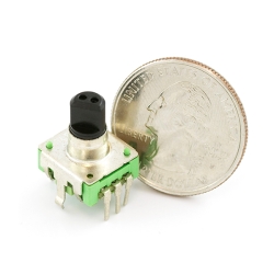
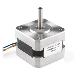
Similar Items


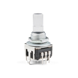
Hookup Accessories


Features & Specs
- Resolution: 1024 Pulse/Rotation
- Input Voltage: 5 - 12VDC
- Maximum Rotating Speed: 6000rpm
- Allowable Radial Load: 5N
- Allowable Axial Load: 3N
- Cable Length: 50cm
- Shaft Diameter: 6mm
Documentation
- Datasheet (E6B2-CWZ3E-1024)
- Example Code
Customer Reviews

Rotary Encoder - 1024 P/R (Quadrature)
$48.50
COM-11102
Stock and Customer Discounts
$48.5 retail price.
Available Discounts
- $46.08 | 25+ units
- $43.65 | 100+ units