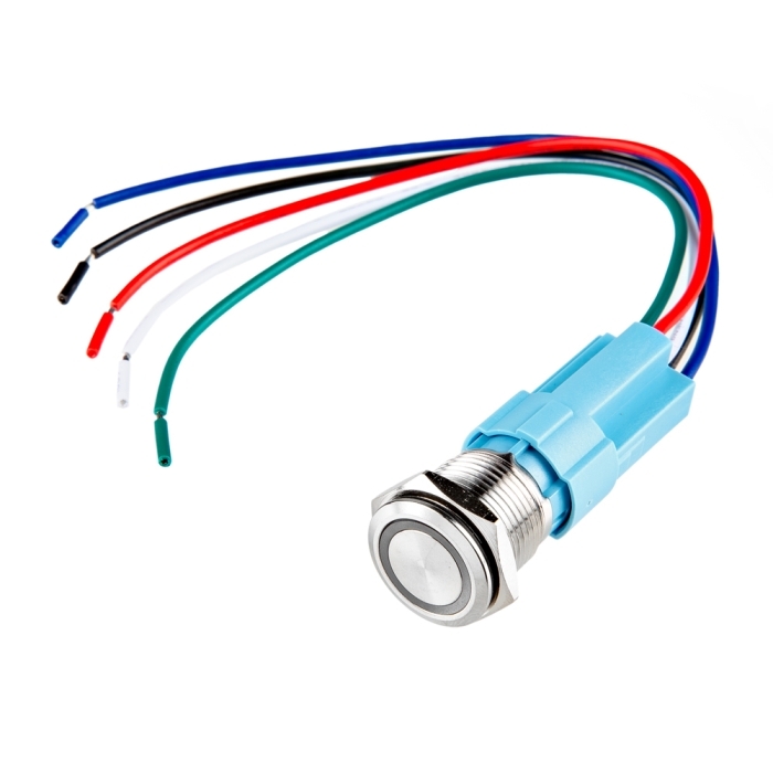
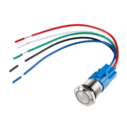
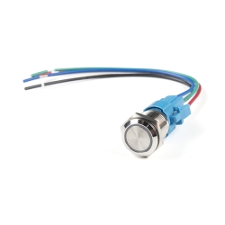
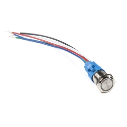
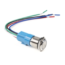
Metal Pushbutton - Momentary (16mm, Blue)

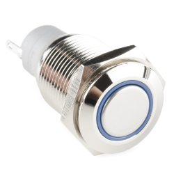
This is a perfect choice if you are in need of a heavy duty push button! These metal push buttons are a very tough, small, panel-mount momentary switch with an illuminated blue LED ring. It is a SPDT with 16mm threading and 1mm pitch. This button is perfect for basic On/Off functions. Overall length (including leads) is 1.5" and has small solder lugs for connection. These momentary buttons are rated up to 3A and 250VAC while the LED is rated for 5-12V.

Note: The images for this button show an LED voltage rating of 5V. We have verified that the voltage range for the the LED to be 5-12V. We are currently communicating with our supplier for new documentation. Trust the branding on the button to verify your voltage requirement.

  • Stainless Steel Body
  • IP65 Weatherproof Rating
  • Tamper Resistant
  • Momentary Operation Type
  • Blue LED Ring

Metal Pushbutton - Momentary (16mm, Blue) Product Help and Resources

Wireless Audio Bluetooth Adapter w/ BC127

December 14, 2017

Build a custom wireless audio Bluetooth adapter using BlueCreation's BC127 and add it to your old speaker system!

Pinout

The pushbuttons (like the momentary https://www.sparkfun.com/products/11966 or latching https://www.sparkfun.com/products/11971 ) have an indication of the pinout of the buttons on the side of the plastic molding. One way to test the switch is to use a multimeter turned to the continuity setting. Here are what the pins (not in any particular order associated with the pushbutton's spades):

+ = LED Anode
- = LED Cathode
C = "Common Ground"
NC = Normally Closed
NO = Normally Open

One way to light the LED on the metal push button would require you to wire it so that when you press down on the button, the led would light up. You would need 5V to light the LED ring. It can be lit up with a smaller voltage but the LED won't light up as bright.

To connect the battery to the button so that it only lights when the switch is pressed down (momentary or latched), you would connect 5V to the "+" pin on the switch. This is assuming that your system is using the same voltage source that is 5V. Then from the "+" pin, you would wire it to the normally open (NO) pin.

Another wire would be connected from the "-" pin to the C pin. The C pin would essentially be connected to your ground. So as you press down on the button, it would flip the switch and complete the circuit from the normally closed (NC) pin to normally open (NO) pin while lighting the LED ring at the same time. It might be a good idea to use a current limiting resistor (like standard 330Ohm resistor) if you are using 5V directly from your power supply. The LED won't be as bright but you also wouldn't be reducing the life of the LED. I am not sure of the electrical characteristics of the LED that is in the pushbutton.


Core Skill: DIY

Whether it's for assembling a kit, hacking an enclosure, or creating your own parts; the DIY skill is all about knowing how to use tools and the techniques associated with them.

1 DIY

Skill Level: Noob - Basic assembly is required. You may need to provide your own basic tools like a screwdriver, hammer or scissors. Power tools or custom parts are not required. Instructions will be included and easy to follow. Sewing may be required, but only with included patterns.
See all skill levels


Core Skill: Electrical Prototyping

If it requires power, you need to know how much, what all the pins do, and how to hook it up. You may need to reference datasheets, schematics, and know the ins and outs of electronics.

3 Electrical Prototyping

Skill Level: Competent - You will be required to reference a datasheet or schematic to know how to use a component. Your knowledge of a datasheet will only require basic features like power requirements, pinouts, or communications type. Also, you may need a power supply that?s greater than 12V or more than 1A worth of current.
See all skill levels


Comments

Looking for answers to technical questions?

We welcome your comments and suggestions below. However, if you are looking for solutions to technical questions please see our Technical Assistance page.

  • noahspylife / about 7 years ago * / 2

    Just to Clarify for beginners and others on Sparkfun:

    C1 - Is the common. NO1 - Normally Open. NC1 - Normally Closed. Right & Left unlabeled pins - LED with (RESISTER ALREADY INSTALLED). So when the button is not pressed: C1 is connected to NC1. When the button is pressed: C1 is connected to NO1. The LED pins can be controlled separately by a microcontroller.

  • Member #1528588 / about 5 years ago / 1

    Why would the datasheet not have an orthogonal view of the solder tab side, indicating which tabs are which? For those of us doing design and documentation before the part arrives, this info is absolutely necessary.

  • Conglacious / about 7 years ago / 1

    Does this switch include any female quick disconnects (solderless terminals)? If not, is there a recommended size to get them elsewhere?

  • sirkha / about 11 years ago / 4

    I feel a need to drop everything and find something to design just for this button. These look awesome.

  • Could anyone tell me - is this button a "snap action" type? That is, does it have a "microswitch" type of action that makes a mechanical and tactile "click" when depressed or released, or does it just use ordinary contacts?

    • Dave McLaughlin / about 9 years ago / 1

      They have a very nice click sound that sounds similar to a micro switch.

      They look great when installed in your panel and the LED ring is very nice and uniform lit.

  • Member #221509 / about 10 years ago / 1

    Do these switches have a nice tactile click feeling to them?

  • Member #576098 / about 10 years ago / 1

    "The three pins for the switch should be labeled on the body itself as C1, NO1, and NC1. The other two pins will correspond to your LED connectors."

    Thanks, can you explain this for a beginner? What is C1, NO1 and NC1? How many volts for the LED?

    • skaterzero807 / about 10 years ago * / 1

      I don't actually have one of these, but it sounds like C1 is connected to NO1 when the button is pressed, and C1 to NC1 when the button isn't pressed. (NC = normally closed, NO = normally open, C = common?)

      As for the LED, the datasheet says 5V but it is unclear if there is a resistor inside already. Based on the picture with all the lights lit up, it looks like you can connect 5V straight to the pins, but you could add a 200-300 ohm resistor in series if you want to be safe. If the LED doesn't come on, you can switch the pin polarity since it could be backwards.

      • emc2 / about 9 years ago / 3

        Just did some testing - I threw a 4.7k resistor inline and dumped 5V across and metered - the LED drops 2.67V at 11.57mA, so that puts resistance at 230 ohms! This thing definitely has a resistor in it already.

        • skaterzero807 / about 9 years ago / 1

          Thanks for checking! I have since gotten the white latching version of this button but haven't pulled it out to test it myself.

  • Member #569304 / about 10 years ago / 1

    Maybe a dumb question.... Do you not need to have a resistor for the LED?

    • emc2 / about 9 years ago / 1

      Nope, resistor appears to be included. See my other comment for numbers.

  • Member #362052 / about 11 years ago * / 1

    Very nice

  • Member #362052 / about 11 years ago * / 1

    Pretty.

  • Member #466360 / about 11 years ago / 1

    I don't see a pinout in the 'datasheet'. Where is the best place to get that data?

    • The three pins for the switch should be labeled on the body itself as C1, NO1, and NC1. The other two pins will correspond to your LED connectors.

  • Member #140775 / about 11 years ago / 1

    Beautiful!

Customer Reviews

4.3 out of 5

Based on 4 ratings:

Currently viewing all customer reviews.

1 of 1 found this helpful:

Greatest button on the market!

This small button packs in a VERY BRIGHT indicator led, which can be controlled separately from a microcontroller. VERY HELPFUL with custom builds. They feature a built-in resistor for the led, and it has a great mechanical build quality, and its click is very professional and industrial feeling.

I recommend you buy this product!

Works so well

I was rewiring a replica-car (52 MGTD on a VW chassis) and needed a pushbutton to control the hi-lo headlight relay and indicate high beam.. I added a 1k ohm resistor to reduce the LED brightness output somewhat

too small for my finger to press

I like the look and quality of this. What I don't like is the button is just too small. It is a challenge to fully depress the button with your finger due to the small size. If they made a larger version of this I feel it would be an awesome product.