SparkFun XBee Shield
The SparkFun XBee Shield mates directly with any dev board that has an Arduino standard footprint and equips it with wireless communication capabilities.
Product Overview
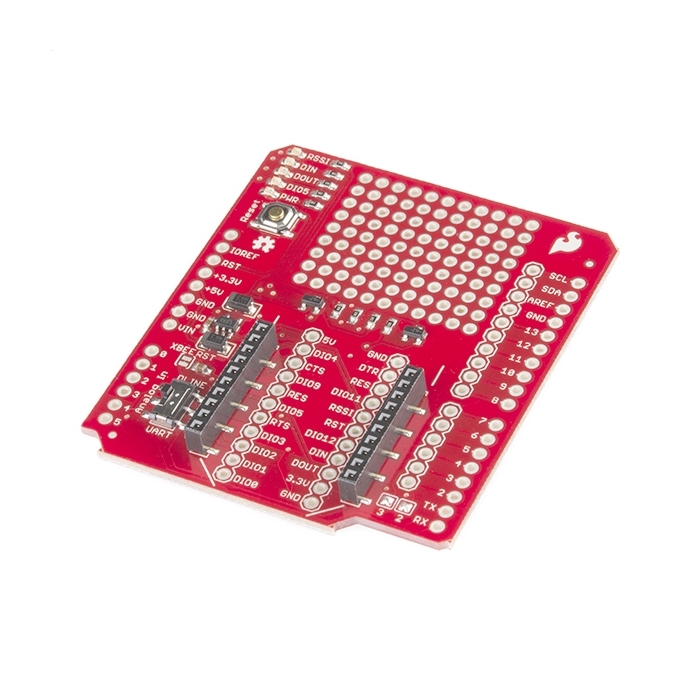
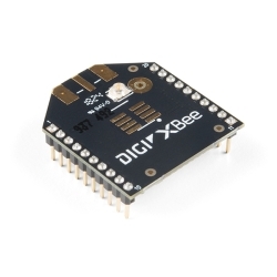
XBee radios are an awesome way to add wireless capability to your Arduino project and now it's even easier with the SparkFun XBee Shield. The shield form-factor mates directly with any dev board that has an Arduino standard footprint and equips it with wireless communication capabilities using the popular XBee module. This unit works with all XBee modules including the Series 1 and 2, standard and Pro versions.
The serial pins (DIN and DOUT) of the XBee are connected through an SPDT switch, which allows you to select a connection to either the UART pins (D0, D1) or any digital pins on the Arduino (D2 and D3 default). Power is taken from the 5V pin of the Arduino and regulated on-board to 3.3VDC before being supplied to the XBee. The shield also takes care of level shifting on the DIN and DOUT pins of the XBee. In the latest revision the diode level shifter is replaced with a more robust MOSFET level shifter.
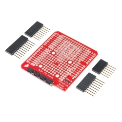
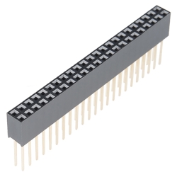
The board also includes LEDs to indicate power and activity on DIN, DOUT, RSSI, and DIO5 pins of the XBee. The Arduino's reset button is brought out on the shield, and a 9x11 grid of 0.1" holes are available for prototyping. The shield does not come with headers installed; we recommend the Arduino Stackable Header Kit. The XBee module is also not included.
Features:
- Mounts directly onto your Arduino
- DIN and DOUT pins of XBee can be connected to either the UART pins or any digital pin on the Arduino (D2 and D3 default)
- 3.3V power regulation and MOSFET level shifting on-board
- 9x11 grid of 0.1" spaced prototyping holes
- Reset button brought out to shield
- Power, DIN, DOUT, RSSI and DIO5 indicator LEDs
Documents:
- Schematic
- Eagle Files
- Hookup Guide
- GitHub (Design Files)


Features & Specs
- Mounts directly onto your Arduino
- DIN and DOUT pins of XBee can be connected to either the UART pins or any digital pin on the Arduino (D2 and D3 default)
- 3.3V power regulation and MOSFET level shifting on-board
- 9x11 grid of 0.1" spaced prototyping holes
- Reset button brought out to shield
- Power, DIN, DOUT, RSSI and DIO5 indicator LEDs
Documentation
- Schematic
- Eagle Files
- Hookup Guide
- GitHub (Design Files)
Customer Reviews

Stock and Customer Discounts
Available Discounts
- $20.43 | 10+ units
- $19.35 | 25+ units
- $18.28 | 100+ units