Using the Arduino Pro Mini 3.3V
 jimblom
 Introduction
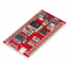
The original, true-blue Arduino is open-source hardware, which means anyone is free to download the design files and spin their own version of the popular development board. SparkFun has jumped on this opportunity and created all sorts of Arduino variants, each with their own unique features, dimensions, and applications. Now one of those variants has landed in your hands; congratulations! It's a wild world out there in microcontroller-land, and you're about to take your first step away from the wonderful -- though sometimes stifling -- simplicity of the Arduino Pro Mini. There are two variants, the 5V/16MHz and the 3.3V/8MHz.

For the scope of this tutorial, we'll go over how to set up and use the 3.3V Arduino Pro Mini, everything from assembling the tiny Arduino to programming it.
Required Materials
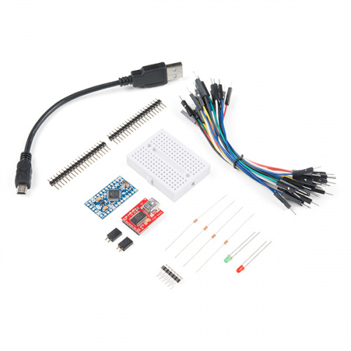
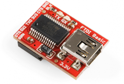
To follow along, you'll need a few extra items. You may not need everything though depending on what you have. Add it to your cart, read through the guide, and adjust the cart as necessary. At a minimum you will need, some headers, USB cable, and FTDI. The FTDI Basic will be used to program (and power) the Pro Mini. The headers are optional, but they're our preferred way to interface other devices to the Pro Mini.

Tools
Assembly of the Pro Mini also requires soldering. This is a great place to start soldering, if you've never done it before! The joints are all easy, through-hole jobs. So grab a soldering iron, some solder and general soldering accessories.


Suggested Reading
This project tutorial builds on a few more conceptual tutorials. If you're not familiar with the subjects below, consider reading through their respective tutorials first:
How to Solder: Through-Hole Soldering
Serial Communication
What is an Arduino?
How to Install FTDI Drivers
SparkFun USB to Serial UART Boards Hookup Guide
How to Work with Jumper Pads and PCB Traces
What It Is (and Isn't)
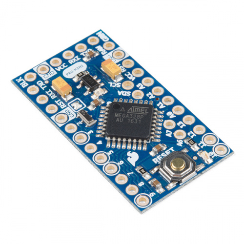
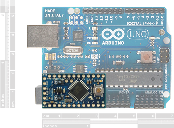
So what differentiates the Arduino Pro Mini from the Arduino Uno? Well, the most obvious difference is the form factor. The Pro Mini's pretty...mini, measuring in at just 1.3x0.70". It's about ⅙th the size of the Arduino Uno. The compact size is great for projects where you may need to fit the Arduino into a tiny enclosure, but it also means that the Pro Mini is not physically compatible with Arduino shields (you could still hard-wire the Mini up to any Arduino shield).
The Mini packs almost as much microprocessor-punch as the regular Arduino, but there are a few major hardware changes you should be aware of before you start adapting your project to the Mini. The first glaring hardware difference is the voltage that the Mini operates at: 3.3V. Unlike the Arduino Uno, which has both a 5V and 3.3V regulator on board, the Mini only has one regulator. This means that if you've got peripherals that only work at 5V, you might have to do some level shifting before you hook it up to the Pro Mini (or you could go for the 5V variant of the Pro Mini).
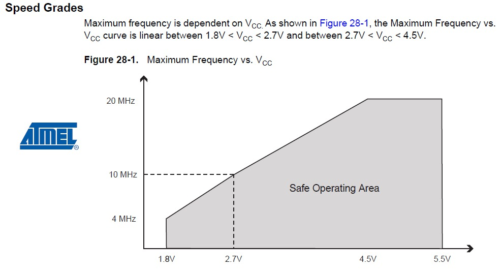
Another major variation from the standard Arduino lies in the speed at which the ATmega328 runs. The Pro Mini 3.3V runs at 8MHz, half the speed of an Arduino Uno. We put a slower resonator on the Mini to guarantee safe operation of the ATmega. That said, don't let the slower speed scare you away from using the Mini; 8MHz is still plenty fast, and the Mini will still be capable of controlling almost any project the Arduino Uno can.
One last missing piece of hardware is the Atmega16U2-based USB-to-Serial converter, and the USB connector that goes with it. All of the USB circuitry had to be eliminated for us to make the Pro Mini as small as possible. The absence of this circuit means an external component, the FTDI Basic Breakout or any USB-to-serial converter, is required to upload code to the Arduino Pro Mini.
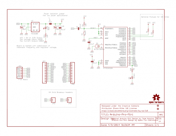
Schematic and Pin-out
The schematic of the Pro Mini can be broken down into three blocks: the voltage regulator, the ATmega328 and supporting circuitry, and the headers.
The Pro Mini's pins surround three of the four sides. The pins on the short side are used for programming, they match up to the FTDI Basic Breakout. The pins on the other two sides are an assortment of power and GPIO pins (just like the standard Arduino).
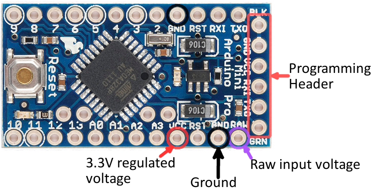
There are three different power-related pins: GND, VCC, and RAW. GND, obviously, is the common/ground/0V reference. RAW is the input voltage that runs into the regulator. The voltage at this input can be anywhere from 3.4 to 12V. The voltage at VCC is supplied directly to the Pro Mini, so any voltage applied to that pin should already be regulated to 3.3V.
Four pins are actually not located on the edge of the board: A4, A5, A6 and A7. Each of these analog pins is labeled on the back side of the board.
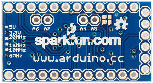
A4 and A5's location may be very important if you plan on using I2C with the Pro Mini -- those are the hardware SDA and SCL pins.
More information about pins can be found in our graphical datasheets. The pinout listed on both datasheets are the same. The only difference is the voltage and frequency that the board operates at.
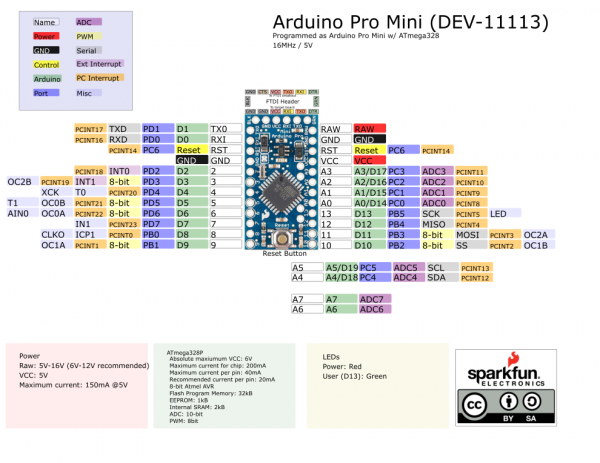 |
 |
| Graphical Datasheet for the 5V/16Mhz Version | Graphical Datasheet for the 3.3V/8MHz Version |
Assembly
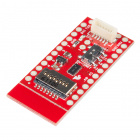
The Arduino Pro Mini doesn't look like much when you first get it; it's as bare-bones as can be. We've left it up to you to solder headers or wires into the open through-holes. There are a few things to make you aware of though.
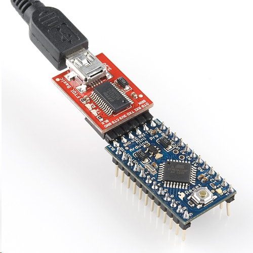
First, decide how you want to connect the FTDI Basic Breakout to the Pro Mini's programming header. The programming header is a row of six pins on the side of the board, labeled "BLK", "GND", "VCC", "RXI", "TXO", and "GRN". Since the FTDI Basic board is equipped with a female header, it's usually best to equip your Mini's programming header with mating male headers, either straight or right-angle.
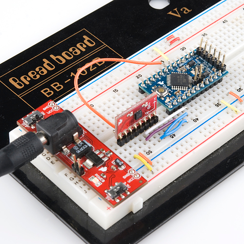
The remaining assembly choices are up to you. There are many options; you could solder in male headers to make it breadboard-compatible, female headers to make it compatible with jumper wires, or just solder stranded-wire straight into the pins.
Versatility is what makes this board so great, and you can assemble it in whatever way makes the most sense for your project.
Powering
The most important factor in any project is what's going to power it. The Pro Mini doesn't have a barrel jack, or any other obvious way to connect a power supply, so how do you power the thing?
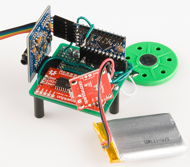
Pick a power source that suits your project. If you want something that matches the compactness of the Pro Mini, a battery -- LiPo, alkaline, coin cell, etc. -- may be a good choice. Or you could use a wall power supply along with a barrel jack adapter.
If you have a supply that's greater than 3.3V (but less than 12V), you'll want to connect that to the RAW pin on the Mini. This pin is akin to the VIN pin, or even the barrel jack, on the Arduino Uno. The voltage applied here is regulated to 3.3V before it gets to the processor.
If you already have a regulated 3.3V source from somewhere else in your project, you can connect that directly to the VCC pin. This will bypass the regulator and directly power the ATmega328. Don't forget to connect the grounds (GND) too!
There is a third power option that's only usually available while you're programming the Pro Mini. The FTDI Basic Breakout can be used to power the Mini via your computer's USB port. Keep in mind that this option may not be available when your project has entered the wild, absent from any computers or USB supplies.
That leads us to the next section...programming the Arduino Pro Mini.
Programming
Arduino IDE
If you've never used an Arduino before (how bold of you to go straight for the Mini!), you'll need to download the Arduino IDE. Check out our tutorial on installing Arduino for help on that subject.
Drivers
If this is the first time that you have plugged the FTDI Basic Breakout into your computer, you may need to install drivers for it. Check out our Installing FTDI Drivers tutorial for help there as suggested earlier in the tutorial.
Uploading Code
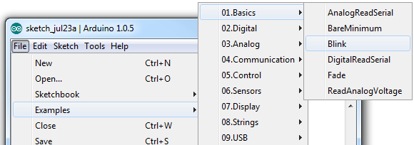
Once both Arduino and the FTDI drivers are installed, it's time to get programming. We'll start by uploading everyone's favorite sketch: Blink. Open up Arduino, then open the Blink sketch by going to File > Examples > 01.Basics > Blink.
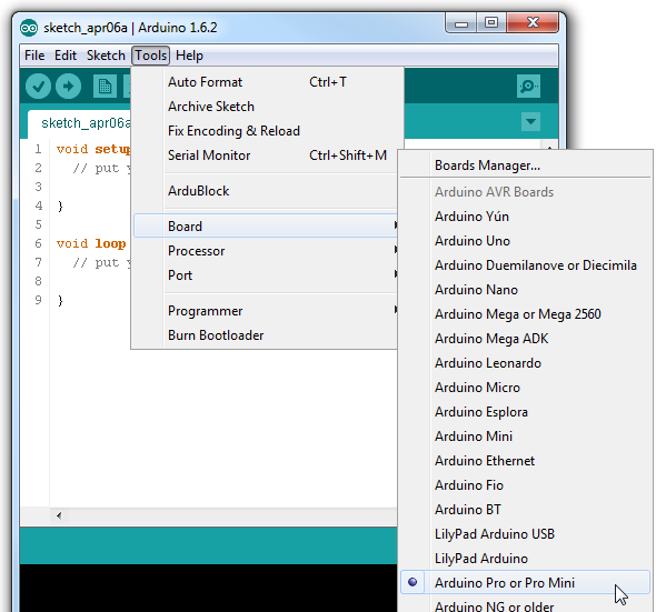
Before we can upload the sketch to the Mini, you'll need to tell Arduino what board you're using. Go to Tools > Board and select Arduino Pro or Pro Mini.
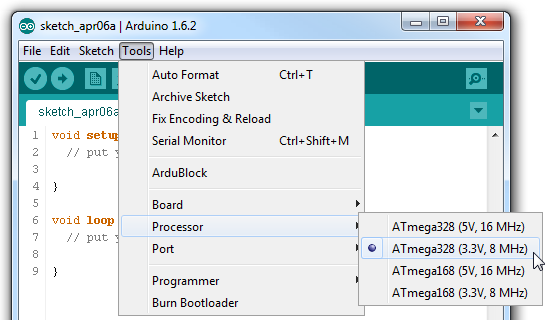
Then, go back up to Tools > Processor and select ATmega328 (3.3V, 8MHz). This tells Arduino to compile the code with an 8MHz clock speed in mind, that way the delay(1000); calls will actually delay one second.
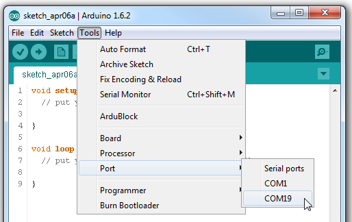
You'll next need to tell Arduino which serial port your FTDI Basic Breakout has been assigned to. On Windows this will be something like COM2, COM3, etc. On Mac it'll look something like /dev/tty.usbserial-A6006hSc.
Finally, you're all set to upload the sketch to your Mini. Click on the Upload button (the right-pointing arrow). After a few moments you should see the red and green RX/TX LEDs on your FTDI board flash, followed by a “Done Uploading” message in Arduino's status bar. Voilà, Blinky! The Mini may be missing a few components, but it's got the most important component: LEDs!
Resources and Going Further
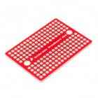
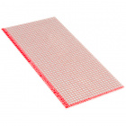
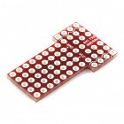
Arduino Pro Mini Prototyping
If you are looking at making a permanent connection, try soldering the Arduino Pro Mini on the following prototyping boards or stacking a shield to the boards.
Like its predecessor, the Arduino Pro Mini is open-source hardware, which means all of the design files are free to view and modify.
- Schematic (PDF)
- Eagle Files (ZIP
- Graphical Datasheet
- GitHub
For more information on the Arduino Pro Mini, first check out our product page as well as Arduino's Pro Mini homepage.
Now that you know the basics of hooking up the Arduino Pro Mini, what project are you going to stick it into? Need some inspiration? Check out some of these tutorials and videos.
- Wake on Shake -- Add the Wake on Shake to provide power briefly to a Pro Mini only when there is a shake or bump.
- The Uncertain 7 Cube -- The Pro Mini is the brains of this fun riff on the magic 8-ball.
- MP3 Player Shield Music Box -- This project uses an Arduino to control the MP3s and motors, but it'd be interesting to swap that out for a Pro Mini.
- Mario the Magician's Magical Lapel Flower -- This project uses a Pro Micro to control the magical flower, but that could be swapped out for a Pro Mini too.
- Interactive Hanging LED Array-- Create a giant LED array driven by the Arduino Pro Mini.
- Reducing Arduino Power Consumption - Reduce current draw on your Arduino project.
- LED Cloud-Connected Cloud - Add the Pro Mini with some WS2812-based Addressable LEDs to light up a cloud for an installation. Better yet, have the Pro Mini talk with the ESP8266 to connect online and have the LEDs react to the weather in your region!
- Raspberry Pi Zero W - If the Pro Mini doesn't have the horsepower you're looking for, consider moving up to a Raspberry Pi platform. The Raspberry Pi Zero provides a smaller form factor.
The Uncertain 7-Cube
Mario the Magician's Magical Lapel Flower
Interactive Hanging LED Array
Wake-on-Shake Hookup Guide
LED Cloud-Connected Cloud
Reducing Arduino Power Consumption
Or check out this blog post for ideas: