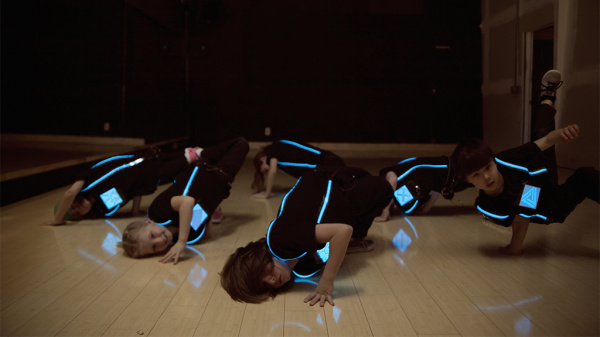
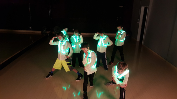
I'm pretty ambitious whenever I get inspired to do a project – after research and testing, I consider the time constraints and how much experience I have doing whatever I'm interested in doing. I then usually take a step back and dial it down to something a bit more manageable. Instead of tackling the whole project all at once, I break it down and complete it in small chunks. This was the case after being inspired by some dancers using EL wire for their performance. In 2014, I started drawing out plans to build some light up costumes for my students at the old SparkFun building. I thought it would be cool and fun for them.
If you remember from my Enginursday post last year, I shared two designs that I used with my students. The first design used EL tape and panels. The second design used non-addressable LED strips.
 |
 |
| Mark I: EL Dance Shirt | Mark II: LED Dance Harness |
Mark III: Motion Controlled Wearable LED Dance Harness
It would have been a shame to not reuse the parts that I spent so much time building for seven students. Instead of designing a new costume, I decided to focus my energy on a small upgrade at their 2016 spring performance with Streetside Studios. For Mark III, I mixed different colors and replaced the custom power adapter with a motion controller. The motion controller used an ADXL335 triple axis analog accelerometer, transistor, and Arduino Pro Mini to switch the LEDs between patterns. It was simple and easy to use. Here's a quick demo of it in action with one of my bboys.
How Do You Build Such a Thing?
Assuming that you have already prepared the LEDs and harness tailored to your size, check out the tutorial linked below for more details on making your very own motion-controlled wearable LED dance harness! Oh and don't be scared of the numbers that I provided after calibrating all eight sensors; they're pretty interesting in my opinion.
Have you ever added an accelerometer or IMU to a wearable project involving dance or movement? Let us know your thoughts below in the comments. Tune in sometime in the future when I show you Mark IV. I'll need a bit more time to explain what I did for the next version. ;D
Interested in learning more about LEDs?
See our LED page for everything you need to know to start using these components in your project.


One other comment: I strongly advise that before you solder any CPU module onto another board, you program each one with at least a "blink the LED" program. Although I've only had this happen once, I had a CPU module that wouldn't program and I only found out after building up the hardware. It wasn't worth the effort of trying to desolder it, especially since OSHPark has a 3-board "minimum order", and I had spares of all the other parts. Anyway, ever since, I've always checked that the CPU module can be programmed before soldering it onto another PCB. (For ProMinis and others this often involves soldering the programming pins onto it. I've never gotten around to setting up a Pogo Pin adapter that I could use to program them without soldering anything to them.)
Our QC tests the microcontrollers out before it heads to our packaging so it should display a simple blink when powered up. With that assumption, I decided to just solder it straight on the board. I did consider having it modular so that I could remove the Arduino Pro Mini but it would have taken more space.
If anything were to happen, I do have some AVR programmers and experience reinstalling the bootloader to try to recover the microcontroller. I'm not sure if I would use the pogo pins with the male headers soldered on certain pins. I would probably use some IC hooks with male header pins if that is the case. That way I would not have to make a test jig and align the pogo pins with Arduino Pro Mini. ;)
I'm sure the QC tests the microcontrollers, but first, I've seen times over the past half century or so when once in a while, one will "slip through", and second, I've also seen "post test failures" in systems (wayward static electricity, and even wayward cosmic rays, can cause such).
As for the AVR programmers, the Pro Mini isn't as convenient as say, the Uno, for use of one, at least not without a special jig which us "mere mortals" are unlikely to have. I bought the aforementioned Pogo Pins with the intent of making a "jig" that I could use with either the 5V flavor or the 3.3V flavor of the SparkFun FTDI Basic Breakout which works well wiith the corresponding flavor of the Pro Mini, and also works well with Adafruit's HUZZAH ESP8266, and save having to solder in the 6 pins for programming on each, but that adapter, like so many other projects, has succombed to the shortage of "round tuits"...
Just as an aside, I happen to have JTAG programmer that I haven't used in years, and a Pi AVR Programmer HAT that I've never gotten around to attaching to a Raspberry Pi.
BTW, I posted my comment above in hopes that some might benefit from my time in the "school of hard knocks", without taking the "courses" themselves. ;-)
The assumption for me when troubleshooting an issue is usually that the boards work and I just happened to miss a step. However, it's always possible that one bad board may slip through (we are human ;D ) or break after testing/cosmic events. This is always in the back of my mind when working with electronics. =)
The Pi AVR programmer Hat is pretty sweet. I was able to test a few out when troubleshooting a few boards.
Maybe 3 years ago I built a "flashy Santa hat" that had, if I recall correctly, 11 Neo-Pixels that responded to head movements. (Unfortunately, it has managed to "disappear" -- I think maybe I took it along with several other items to a "demo" and it didn't manage to come home.)
Another project, although it didn't involve "flashy lights", did involve two 3DOF IMUs. When recovering from a broken wrist, I was prescribed this "brace" that would apply (gentle) pressure to twist my wrist to try to regain movement. I found the directions rather nebulous, and couldn't come up with a practical indication of how much "twist" I'd applied that I could read while wearing the thing. (You put the brace on at "zero twist", and then you start cranking it.) I figured out how to use two IMUs, one attached to the "fixed" portion of the brace and the other attached to the "rotating" portion to calcuate the "twist angle". For a CPU and display, I used a MicroView. It displayed the angle, and included a timer to help with knowing how long I'd been wearing it this session. I approached the brace manufacturer, and they were NOT interested, saying that it would have to go through FDA approval -- your tax dollars hard at work! Oh well...
I forgot to mention that I used digital 3DOFs from Adafruit for both these projects. They are easy to deal with under I2C, and even have address select line, allowing me to put both IMUs on the same I2C bus.
Yeah, I remember you had talked about that flashy Santa hat build. Hopefully you find where it disappeared. The IMU brace sounds like a cool project.