- Home
- Product Categories
- Monochrome
- Basic 16x2 Character LCD - White on Black 5V

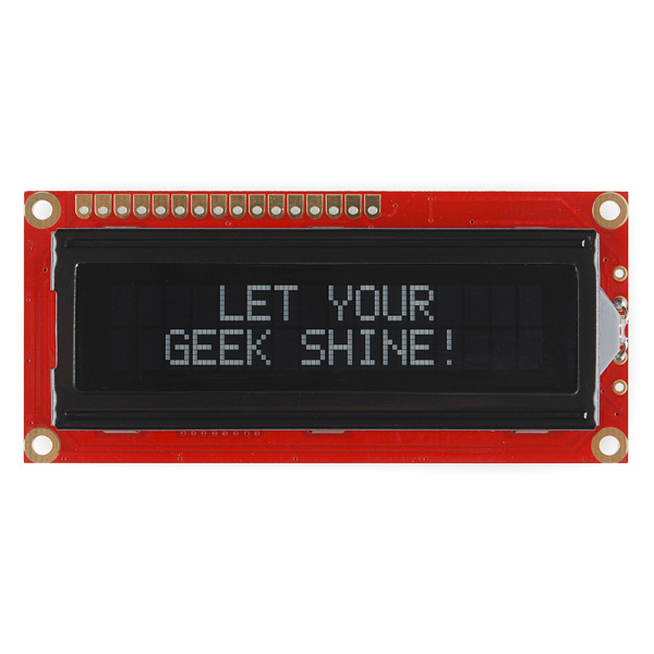
Basic 16x2 Character LCD - White on Black 5V
This is a basic 16 character by 2 line display with a snazzy black background with white characters. Utilizes the extremely common HD44780 parallel interface chipset (datasheet). Interface code is freely available. You will need ~11 general I/O pins to interface to this LCD screen. Includes white LED backlight.
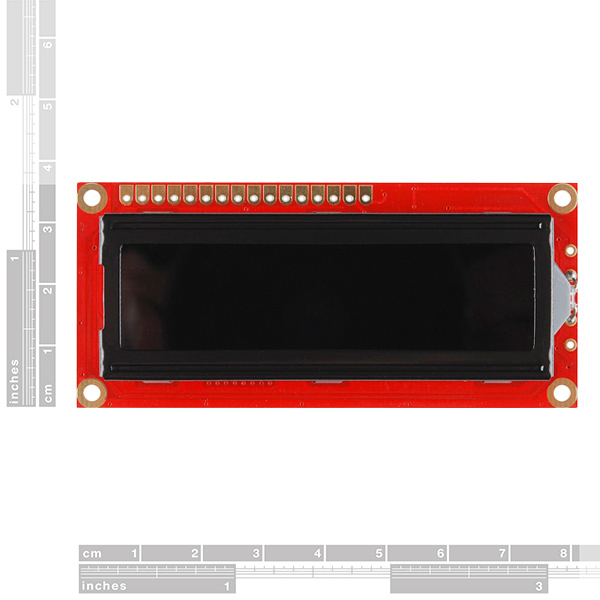
- 3.15" x 1.425"
Basic 16x2 Character LCD - White on Black 5V Product Help and Resources
PIC-Based Serial Enabled Character LCD Hookup Guide
May 29, 2018
The PIC-based serial enabled character LCD backpack is a simple and cost effective solution for interfacing to character Liquid Crystal Displays (LCDs) based on the HD44780 controller. The backpack simplifies the number of wires needed and allows your project to display all kinds of text and numbers.
Experiment Guide for the Johnny-Five Inventor's Kit
June 28, 2016
Use the Tessel 2 and the Johnny Five Inventors kit to explore the world of JavaScript enabled hardware through 14 awesome experiments!
Endless Runner Game
November 28, 2017
We make a simple side-scrolling endless runner game using parts from the SparkFun Inventor's Kit v4.0.
SparkFun Inventor's Kit Experiment Guide - v4.0
November 15, 2017
The SparkFun Inventor's Kit (SIK) Experiment Guide contains all of the information needed to build all five projects, encompassing 16 circuits, in the latest version of the kit, v4.0a.
Basic Character LCD Hookup Guide
May 28, 2019
Liquid crystal displays (LCDs) are a great way to output a string of words or sensor data to a display for visual feedback. In this tutorial, we'll learn about LCDs, how to print a string of words to a 16x2 basic character LCD and create custom characters.
SparkFun Inventor's Kit Experiment Guide - v4.1
August 8, 2019
The SparkFun Inventor's Kit (SIK) Experiment Guide contains all of the information needed to build all five projects, encompassing 16 circuits, in the latest version of the kit, v4.1.2 and v4.1.
Core Skill: Soldering
This skill defines how difficult the soldering is on a particular product. It might be a couple simple solder joints, or require special reflow tools.
Skill Level: Noob - Some basic soldering is required, but it is limited to a just a few pins, basic through-hole soldering, and couple (if any) polarized components. A basic soldering iron is all you should need.
See all skill levels
Core Skill: Programming
If a board needs code or communicates somehow, you're going to need to know how to program or interface with it. The programming skill is all about communication and code.
Skill Level: Rookie - You will need a better fundamental understand of what code is, and how it works. You will be using beginner-level software and development tools like Arduino. You will be dealing directly with code, but numerous examples and libraries are available. Sensors or shields will communicate with serial or TTL.
See all skill levels
Core Skill: Electrical Prototyping
If it requires power, you need to know how much, what all the pins do, and how to hook it up. You may need to reference datasheets, schematics, and know the ins and outs of electronics.
Skill Level: Competent - You will be required to reference a datasheet or schematic to know how to use a component. Your knowledge of a datasheet will only require basic features like power requirements, pinouts, or communications type. Also, you may need a power supply that?s greater than 12V or more than 1A worth of current.
See all skill levels
Comments
Looking for answers to technical questions?
We welcome your comments and suggestions below. However, if you are looking for solutions to technical questions please see our Technical Assistance page.
Customer Reviews
4.2 out of 5
Based on 13 ratings:
0 of 4 found this helpful:
La primera que recibí se me estropeó
Tuve que cambiar la primera que compré porque empezó a oiscilar la iluminación de la pantalla.
Por lo demás todo muy bien, buena presentación y buen funcionamiento.
Saludos,
I love these screens.
The display is clear and the characters are legible. I do wish this display supported more than 32 characters. As for interfacing, that is very easy. Just a hand-full of switches (and one potentiometer) and an ASCII chart you don't even need a microcontroller (but you'll only be able to print one character every few seconds without one).
Fantastic!
Display is Much brighter than the picture, and even though it was a bit scary to solder onto (im a bit of a newb at soldering) , it works fantastic! So bright, Very responsive. I dont even have the display at its brightest and it is a crystal clear read! Look forward to using it in my summer project.
Good Quality LCD
The LCD arrived promptly in the mail and worked as advertised. If my experience is typical of Sparkfun, they have good products and are very efficient.
Strait Forward
I wired up the display and ran it with the standard Arduino library. Worked first time!
Narrow viewing angle, Color Inversion
Apparent color changes from white-on-black to black-on-white at ~ + 5’ and ~ -20’. Readable until ~ + 35’ and ~ - 80’. During the color change, it’s difficult to read; a lot of head bobbing is required. Readability at greater + angles would be better for my application. Is there any way to flip the text orientation or, perhaps, another hack to improve upon this issue? I won’t be purchasing this product again.
0 of 2 found this helpful:
Shipped defective,,didn't work
Hello!
Sorry to hear about the issues with the LCD screen. Have you contacted our technical support department @ techsupport@sparkfun.com - they're usually great at helping sort out defective products for people and getting them working components.
The contrast is ideal for viewing, day or night
I used this display in a DDS VFO. The contrast of the display is great for viewing at any angle day or night
Basic 16x2 Character LCD - White on Black 5V.
This LCD works as advertised. The software compiles from the Arduino library only for version 1.0.5-r2. These LCD units are well made, but do not drop them on a hard surface as the electronic seal to sensitive glass surface will fail to make proper contact. Most of the test examples in the Arduino library work great. My unit shows black on white.
Looks great. Works great
I bought it to fit into a homebrew DDS-based VFO for my vintage ham station. Most of the various color displays just don't look right with all the dark somber enclosures of the period. This mostly monochrome LCD fits in fine if one can accept a DDS device in a tube environment.
https://photos.app.goo.gl/RQCwAVbczprl7F3G3
But it's certainly bright and showy INSIDE with it's red PCB.
Eric KE6US
No Issues
Works fine with a Raspberry Pi 3 an the white on black look really nice.
works well
its does exactly as required. easy to use and mount
Couldn't be happier
Works as it's described, would recommend to anyone. And if any issues sparkfun support can help as they did for me. Overall satisfied
Everything you need to know to make this work:
Code:
Wiring diagram:
The 3.3kΩ resistor replaces the potentiometer (at least for me).
Example code
Perfect!!!
Thank you
"The 3.3kΩ resistor replaces the potentiometer (at least for me)." I'm using 2 1K resistors with the the contrast in the middle. You can see some stuff you're not supposed to, but it's clear none the less.
What are the solder jumpers J1-J6 on the back?
Does anyone know where I can find information on the empty surface mount pads on the back of this board? Seems like I should be able to save some wiring if I can use those.
For those having problems try this. With the pins at the top pin 1 is next to the edge. I'm using an Arduino ATMega 328 mini pro.
using the example Hello World arduino sketch.
PIN1 = tie to gnd
2 = tie to 5v
3 = resistor ~2-3K to gnd
4 = rs = tie to pin 12 on arduino
5 = r/w = tie to gnd
6 = enable = tie to pin 11 on arduino
7-10 = open (no connections)
11 = tie to pin 5 on arduino
12 = tie to pin 4 on arduino
13 = tie to pin 3 on arduino
14 = tie to pin 2 on arduino
15 = tie to 4.2 V (5V is working for me right now)
16 = tie to gnd
using this with an arduino will work
You are the BEST!!! Thank you. It was worth registering just to post this message to you. I hope to participate further. There are a LOT of bugs in the Arduino sketches (Projects 1-23). Thanks again. Arnold
I made a tutorial (in portuguese) about how to use, create custom characters and design menus for the LCD display. Take a look: http://engenheirando.com/arduino/displaylcd/
I'm after a 20x4 version of this white on black display. Can't seem to find one anywhere. Does such a beast exist?
I would also be interested in a 20x4 version!
Working OK with Picaxe 20x2 but uses pins I would like to have free for i2c. So, I am getting bigger picaxe to go with it. Used 2 rectifier diodes in series for the voltage drop to 4.2v on the backlight and two 1k ohm resisters in series for the contrast. Looks good.
Thanks loophole! I got the display working fine using this link that link that was mentioned, http://arduino.cc/en/Tutorial/LiquidCrystal, but it was dim since the backlight was not working. After reading loophole's comment and looking at datafile I applied 4.2V pin 15 and grounded pin 16, and all was GREAT!
Note: To get around 4.2V I just ran it through two IN4004 diodes.
Works fine with Arduino and LiquidCristal library.
Needs a lcd.clear() in void setup()
And don't just ground the contrast (V0), use a pot or you won't be able to read anything.
How bright is this? I would like to leave it on in the dark but not have it too bright such that it looks like a light source. I'm considering getting this vs. the standard black on green since it looks nicer but hoping its not too bright in the night.
I already fried one while soldering on the headers, now I think I ruined a second one. I have it wired up the way KHartley describes, but I only get backlight, no text, even when simply uploading the Hello World example sketch. Assuming I didn't destroy it, does anyone know why this might be?
Play around with the trimpot setting. If you still aren't getting any results, make sure you don't have any solder jumpers between pins.
Could some one please tell me how to turn on the lcd backlight? Thanks to anyone for any suggestions
This display looks sooooo much nicer than the standard blue/white or green/black combo. It's well worth the extra few bucks.
LCD works for 2 minutes and then the screen dims…… wired as instructed in the SIK guide. Any ideas?
The post that KHartley posted with regards to all the pin connections and using an Aduino mini pro, who then also got a reply from member 468163, that the code and everything worked.
I am using the exact components and have followed the exact pin configurations for the past 2 weeks, connecting then reconnecting, I have also tried different FTDI cables for uploading onto the Arduino pro mini. BUT have had no success, PLEASE help me as it is a basic issue I am sure but cannot find the solution, My 16*2 LCD lights up and also when I upload a program the arduino page reads that it has successfully uploaded (Done Uploading).
I have seen that the other alternative or different way of setting up the circuit is by using a resistor instead of the 10K potentiometer that I am using.
Any suggestions?
Here's a tutorial on creating custom characters with Arduino on instructables => http://www.instructables.com/id/Controlling-a-character-LCD-with-an-Arduino/?ALLSTEPS.
Hey. looking to find a good mounting solution for this onto a project box. Any suggested DIY projects or prefab bezel solutions for a professional look?
We've had customers order face plates through Ponoko for these LCDs and be pretty happy with it. Check around on the comments on other products and on the forum. You'll probably find a lot of different examples of mounting solutions.
can this run in 8bit mode? I'm trying so hard to just wire up the 8 data lines and manually send the bits required for certain symbols. But it's either stuck in 4bit mode, or I'm completely lost. My program is simple and I KNOW that it is sending the 1's and 0's down the appropriate lines but I can't get a response at all. And I can succesfully apply the example code for liquid crystal. In class we just banged some bits into those old lcd's and got the expected response... Is this one more advanced or something? Thanks, I really appreciate any help.
No matter what line I set the cursor at using lcd.setCursor(0,0), or lcd.setCursor(0,1), it will print everything on line 0. I've used the same LCD, different size before and never had this issue.
Any Ideas?
Could the library be changed to display the Japanese characters as seen in the extended datasheet?
I'm trying to find a 16-pin ribbon connector for this display. Do you guys know of where I can find one?
FYI, currently, you can get this plus header pins and a potentiometer at the link below, for the same price.
https://www.sparkfun.com/products/10054
This is A good tutorial in Arabic language how connect it wth arduino How connect arduino with lcd
لقد وجدت هذا المثال مشروح في اللغة العربية عن كيفية توصيلها مع الاردوينو
You should make the LCD's connection pins on the bottom, like on the RGB backlit LCD's (https://www.sparkfun.com/products/10862). I like standing them straight up and down on breadboards. If I tried that with this one, it would be upside down.
Can someone help with the backlight spec? The wrong datasheet is posted (assumes multi-LED backlight 4.2V@160mA)
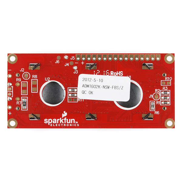
My LCD is marked "ADM1602K-NSW-FBS/Z". It's a single white LED w/on-board 130R series resistor- measures 16mA at 5V across Pin15-16
Does anyone know where I could buy the 16x4 or 20x4 version of this LCD? I'd like one with the same white on black style.
Just in case there are any n00b, like me, out there struggling with this thing. The LED is 3.3V but everything else is 5V.
I've worked with these for a little bit now and it is a very nice looking display, and works well with arduino.
has anyone measured the amperage on the backlight?
my lcd is working fine.
and the backlight only needs 15mA @ 5V without any resistor involved...
can anyone verify this?
yes. I've measured the same: 14mA @ 5V and the led get's 3.1V so I connected the pin 15 to a pwm pin an pin 16 to gnd an it works fine!
Which part in eagle should I use for this?
I can't find a 16 pin header for this lcd in the Sparkfun library.
a little, or very very late, but the part name is LCD-16X2 in eagle. or you can do a search like 16X2
Thanks
Woa, what are the odds of that? I was just looking for the eagle part for this not 2 minutes ago. Thanks.
I'm having a problem with this lcd, I can'd print custom caracters, I tried the code that this site http://icontexto.com/charactercreator/ gives you when you create a custom char, tried some other examples, but nothing, I always get just two vertical bars on the second and fourth columns.
Is it a compatibility issue with this controller (it's a SPLC780D, not a HD44780 as said in the description).
BTW, it can display normal characters just fine.
I love this little LCD! It works great. However, I'm having a wicked hard time finding hardware (i.e. self-clinching PEM stud) that I can use to mount this. The 2.5mm mounting holes are pretty small. I'm trying hard not to use glues.
Any suggestions, anyone?
Thanks in advance. :)
I'm having problems with my contrast - it's always either too high (washed out characters) or too low (can't see the character) on separate spaces at the same time. No matter how I adjust it, each character seems to require a different contrast level. Help, please?
I'm also having problems with contrast; I'm using a 10k pot on the contrast pin, and it takes tiny adjustments to make it work. After a minute or so running, the contrast starts to flicker, and I can't seem to get it stable.
An RGB backlit version would be AMAZING!
They look relatively inexpensive too:
http://www.mouser.com/ProductDetail/Newhaven-Display/NHD-0216K1Z-NSRGB-FBW-REV1/?qs=sGAEpiMZZMt7dcPGmvnkBh7HNOkOcI5QdW24NKaHSg4%3d
I'm also having trouble with LCD. I hooked up at 10kOhm pot, but when I upload the code it just gives me random pixels and characters. Is my Atmega on my Arduino Uno shot?
out of stock...anyone know where else to get these? I tried google and can't find any other suppliers.
for PIC directly, but you can implement driver for any microcontroller easily using mine as a base...
its just digital output high/lows so lol
http://joekwuen.blogspot.com/2011/02/project-hd44780-textual-lcd-driver-for.html
Like others have said, works well with liquidcrystal library and I also like to pwm the backlight with a fet on the low side. Looks really cool to have it fade out to 1 or 2% duty cycle standby mode when there has been no button presses/input in a while and then fade back in when you press a button.
Also no external resistor is needed for the backlight; just like almost all other 5v character LCDs this one has a series resistor right on the board. Mine is 130 ohms.
I like the sound of this. Don't suppose you could post a quick sketch of how to wire up the fet for us beginners to use as a guide? Thanks!
Very Awesome display! It fired up and worked for me first try using the Arduino Liquid-Crystal library.
Strongly recommend using this display!
Hello everyone.
Can anyone here give me a schematic that shows how to connect the above lcd with one atmega328
running arduino bootloader (just the chip not the whole
dev board,on a breadboard)
If you had searched the arduino website you would've found this:
http://arduino.cc/en/Tutorial/LiquidCrystal
The mbed example that is listed is not using serial. Setting up the serial with mbed is quite easy though.<br />
<br />
Serial lcd(p13,NC); // NC = not used
Works Great! Used with the Arduino and LiquidCrystal. Very clear and easy to read. I originally was setting contrast with a PWM pin to see how it worked(AKA I forgot to buy a trimpot), but it made the screen 'pulse'. Switched to a potentiometer I scrounged and that worked much better. Ive got the backlight hooked to +5 and its been working fine so far.
I was able to achieve much better contrast by applying a slightly negative voltage on the Vo pin (3). Minus 200 mV did the trick. I seem to remember that LCD's used to have a negative output for just this reason. I don't know what the rating of this pin is, so proceed with caution.
For those of you trying to hook up the LED backlight, here are some things to consider:
1) The spec sheet says 120mA typical, 160mA max. for the backlight.
2) The backlight is a 4.2V forward biased LED, so pin A (or 15) is the anode and K (or 16) is the Cathode.
3) If you hook it to an Arduino, powering the LED backlight from a digital I/O pin will only source 40mA max. (PIC micros are even less), any more and you are overloading your output. Tie pin K (or 16) to ground, and A (or 15) will be the high side. If you design for 40mA, calculate the current limiting resistor to put between the I/O pin and pin A (or 15) of the LED backlight as follows: 5V-4.2V=0.8V and 0.8V/0.040A=20ohms however, be sure to measure the voltage across your current limiting resistor and calculate the actual current flowing to the LED just in case... don't overload your Arduino I/O!
(more continued below...)
4) If you want to really drive it properly, you need more POWER! So grab an NPN transistor such as a 2N4401 or 2N2222 or 2N3904, and amplify your I/O. Hook a 220 to 330 ohm resistor between your I/O and the base of the NPN, hook the emitter of the NPN to ground, and the collector to the K pin (or 16) of the LED backlight. Hook a 5 to 10 ohm 1/4W resistor between the A pin (or 15) of the LED backlight and the 5V rail (make sure your 5V regulator can handle the extra 120-160mA of current you are going to be consuming)
what is the reason for the 5-10ohm resistor between the anode and the 5v? Someone mentioned that there is already a 130ohm resistor on the board in series with the backlight LED, so i can't find a reason for it being there.
Oh, almost forgot... if you make that I/O a PWM output... you can then vary the brightness from 0-100%
Got it working with this tutorial
http://www.hacktronics.com/Tutorials/arduino-character-lcd-tutorial.html
Thanks to the guy who did that wiring up diagram at Aruduino.
Thanks to the guy who first pointed that for that bcklight to work one needs pin 15 on +4.2V and pin 16 on ground. Without that I was getting a pretty dim job.
For me, 82ohm resistor produced exactly 4.2V, on the pin 15. 10ohm resistor was giving me around 4.8V. Since I've no clue, better safe than sorry.
It is a brilliant little LCD. Really looks cool. I bought it for the looks ;-)
yeah, I've got a 110ohm on it. Still very bright, reading 3.8v or something in that ballpark.
This things freakin' great.
I made it work by using the same schematic featured in the LiquidCrystal Arduino library page, except LCD pin 6 is hooked to a digital PWM instead of a potentiometer for controlling contrast.
I used a 10ohm resistor for pin 15 to drop the backlight voltage, it works great and looks just like the picture. Pin 16 is hooked to ground.
Very nice, bright, easy to use LCD!
Pretty cool little LCD. I had some problems initially with the 4bit LCD library, but after finding that the standard LiquidCrystal library supports 4-bit data lines it worked great.
The one thing that threw me off was that the standard (not extended) datasheet mentions that the backlight (BKL) can be driven by pins 1,2 or 15,16 -- however I found that I needed to apply 4.2v to pins 15,16 before the backlight would work. Easy fix, just misleading on the datasheet.
I'm very impressed. I followed the connections from the data sheet and set them up the same way the LiquidCrystal "Hello World" example sketch calls for, and the display worked perfectly with my Arduino Duemilanove. It does take some playing with the contrast potentiometer, but I quickly found the perfect setting. The display is sharp, clear, and cool white letters on a black background.
Ordered mine a week ago and finally got around to playing with it. I used the included LiquidCrystal.h for Arduino to run this thing. Very easy to use once you get it up and running. To get the contrast working I used a 3.3Kohm resistor going to ground, looks amazing. Not quite as bright as picture but I think I'm close. 2.2Kohm is too washed out and 6.8 Kohm nothing shows up. I can't believe how much easier this is compared to the 68HC12. Uhhh, I'm going to have nightmares for the rest of my life.
Hey I'm thinking of buying one, but I'd like to know. How bright is it, I'm thinking of using it on a buggy to show fuel, tack, and speed. So it will be vibrating around in bright sunlight. My question is, will it be legible?
Thanks.
Characters on mine look very dimmed! I'm using a potentiometer, however when powered up doesn't look anything like the product image thumbnail.
I'm following the schematics from Arduino website: http://arduino.cc/en/Tutorial/LiquidCrystal
It works fine with my second LCD (black on green) but not with this one (white on black).
Am I missing something?
Have you wired in the backlight? That tutorial doesn't include wiring pins 15 and 16 on the lcd. I have hooked the backlight up to a pwm output so that I can turn it on and off via sketch.
Hope this helps.
Denny
Hey Montini,
Shoot us an email (techsupport at sparkfun dot com), and give us as much info as you can. We'd be happy to help troubleshoot.
I am also ahving this same problem. The LCD was great and easy to set up, but the brightness is really really poor. I installed a pot and all, but no dice.
The LCD display is barely visible without the back light. If you connect the back light it'll look like the photo in the product info.
Does anyone have a recommended source for a mounting bezel faceplate for this display?
nvm the pdf above not only has the dimensions but also the tolerances! nice
are the above dimensions the lcd itself or the actual part?
You can check the datasheet for measurements ;) EDIT: Sorry, didn't see it was a 4 year old comment. Aaand you already said it yourself - Im a tool...
Has anyone got this working with the LiquidCrystal or LCD4bit library? I am having quite a bit of trouble getting it to work reliably and am at the point where I am going to try and code my own library for it.
I'm also having heaps of trouble. I can sometimes get it to display text, maybe once out of every 30 attempts. And IF it decides to display anything it ends up garbling the message and locking up, not displaying the other strings in the sequence. Is this the LCD, my Arduino or the library? I tried using LCD4bit and a modified LiquidCrystal and they all yield the same, frustrating results.
I have this same issue. I have to try many, many times to get it to work. Do you have any suggestions.
Late reply, but I have trouble with this if I forget to add decoupling capacitors on the V+ line. Especialy using multiple serial to parallel converters at high data rates.
Nice bit of kit : )
Great little lcd, for basic output, debugging etc. Very easy to interface, and looks very slick! If you need a basic no frills LCD, this is a good buy.
Great Product! I am a arduino newb and got it up and running in no time. I would love to be able to power this with a battery...anyone try this?
What do you mean? Power is power buddy. Just make sure you regulate it as needed.