- Home
- Product Categories
- 7-Segment
- SparkFun 7-Segment Serial Display - Red

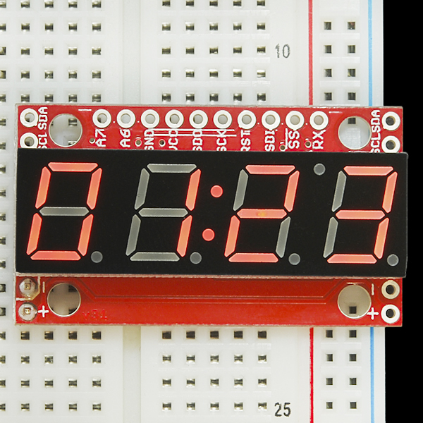
SparkFun 7-Segment Serial Display - Red
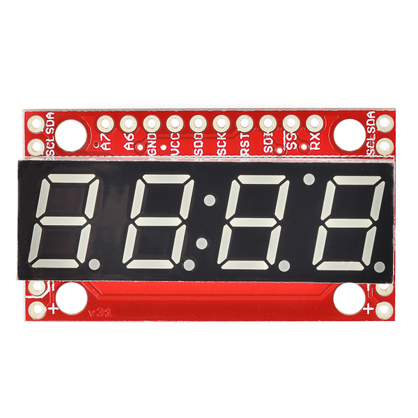
4-digit 7-segment displays are really neat little devices, it's a shame that they can be so cumbersome to control. Well we've solved that problem by making them a little bit "smarter." The SparkFun 7-Segment Serial Display combines a classic 4-digit 7-segment display and an ATMega328 microcontroller allowing you to control every segment individually using only a few serial lines.
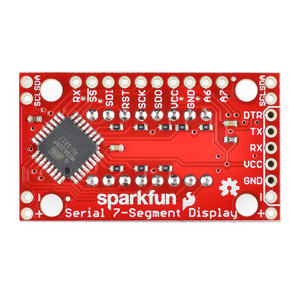
The Serial 7-Segment Display can be controlled in one of three ways: Serial TTL communication, SPI serial communication or I2C serial. You can even program it for stand-alone operation since the ATMega328 comes pre-loaded with the Arduino bootloader! There is also an FTDI header on board and we've provided a hardware profile for the Arduino IDE to make it even easier to program.
We've made some layout changes to this design as well which will make it easier to incorporate these into your project. We've moved the power and I2C pins to the sides of the board such that you can chain them together in order to display longer strings of digits. We've also added mounting holes to the boards so you can mount them on standoffs (no more hot glue!)
Replaces:COM-09766
- 4 digit red alpha-numeric display with TTL, SPI or I2C Serial Interface
- Display numbers, most letters, and a few special characters
- Individual control of decimal points, apostrophe, and colon
- Selectable baud rate
- Selectable brightness
- Baud rate and brightness values retained in non-volatile memory
- Individual segment control for each digit
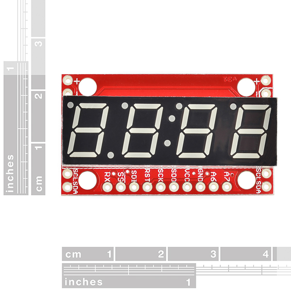
- 41mm x 23mm (1.6in x 0.9in)
SparkFun 7-Segment Serial Display - Red Product Help and Resources
IoT Weight Logging Scale
May 9, 2018
This tutorial will show you how to make a scale that logs your weight to a custom website on the Internet. The principles can be extrapolated to any type of data.
Dungeons and Dragons Dice Gauntlet
August 13, 2013
A playful, geeky tutorial for a leather bracer that uses a LilyPad Arduino, LilyPad accelerometer, and seven segment display to roll virtual 4, 6, 8, 10, 12, 20, and 100 side dice for gaming.
Using the Serial 7-Segment Display
August 13, 2013
How to quickly and easily set up the Serial 7-Segment Display and the Serial 7-Segment Display Shield.
Raspberry Pi SPI and I2C Tutorial
October 29, 2015
Learn how to use serial I2C and SPI buses on your Raspberry Pi using the wiringPi I/O library for C/C++ and spidev/smbus for Python.
Core Skill: Soldering
This skill defines how difficult the soldering is on a particular product. It might be a couple simple solder joints, or require special reflow tools.
Skill Level: Noob - Some basic soldering is required, but it is limited to a just a few pins, basic through-hole soldering, and couple (if any) polarized components. A basic soldering iron is all you should need.
See all skill levels
Core Skill: Programming
If a board needs code or communicates somehow, you're going to need to know how to program or interface with it. The programming skill is all about communication and code.
Skill Level: Rookie - You will need a better fundamental understand of what code is, and how it works. You will be using beginner-level software and development tools like Arduino. You will be dealing directly with code, but numerous examples and libraries are available. Sensors or shields will communicate with serial or TTL.
See all skill levels
Core Skill: Electrical Prototyping
If it requires power, you need to know how much, what all the pins do, and how to hook it up. You may need to reference datasheets, schematics, and know the ins and outs of electronics.
Skill Level: Noob - You don't need to reference a datasheet, but you will need to know basic power requirements.
See all skill levels
Comments
Looking for answers to technical questions?
We welcome your comments and suggestions below. However, if you are looking for solutions to technical questions please see our Technical Assistance page.
Customer Reviews
4.4 out of 5
Based on 16 ratings:
1 of 1 found this helpful:
Works Just Fine wit 5 V Arduino
A previous comment indicated dim output. With a 5 V Arduino Uno this was very bright. I actually cut back a little on the brightness by setting it at about 75% through the software. I found the documentation pretty good. I had to get more information, but that was because I'm not very good at serial protocol. I think this is a good product and will be ordering a couple more for some other projects. Thanks.
1 of 1 found this helpful:
Nice display
I used this for a clock/thermometer running from a PI 3. The serial TTL was very easy to interface. Adjustable brightness was useful. I would have liked a slightly larger display but that was not available.
1 of 1 found this helpful:
So easy !
Used two I2C controlled displays. So easy to use thank to the Wire library.
The only drawback: a weird letter "P", looking as an inverted "g", easy to correct by code.
open-source project here: https://eliadarkroom.wordpress.com
0 of 1 found this helpful:
Handy-dandy
As an exhibit designer/fabricator, I use these things quite often. They're flexible (I usually use either SPI or I2C) and robust. Together with the big-brother version (COM-11644) they are very useful anyplace we need digital timers/displays.
Awesome little device!
I got a red one and a green one. These are great! I've tried out about 1/2 of the features so far. One thing that's really useful is that is has both decimal points and a colon. Whenever I need a small 7-segment display I'll use one of these
Works perfectly
Easy to set up.
These 7segment serial displays are truly a game changer!
They are easily adaptable to many projects regardless if your using Arduino or Raspberry Pi control platforms...Plan to use them in my customized hand controls for years to come!👍 Vic Rizzo RIZZO CONTROLS LLC
0 of 1 found this helpful:
I2C control
I have good control with I2C with this right now. But be warned is a bit sensitive to static and noise. Since I decided to write a clock in VB6 for testing this, constantly updating the display (every 100 ms move decimal point, and every half second flash colon) when I moved with with my hand it apparently got garbled. Since I was using an Ardvark interface, and had the pull up's on it turned on, maybe I should have had resistors on the end near the board instead. But what happened is somehow it read it as a change I2C address. So I wrote a change to my vb program and found it had changed to address 181, which I found interesting.
None the less a fun and very inexpensive display to work with.
Also wish intensity control 0 would be totally off and not have to blank the display if you want it all not be be seen. But this is a personal preference. And most likely I could rewrite the software to do this myself.
The nice thing about this is the excellent documentation. I may use these chips for replacement where I would normally use a MAX1447/MAX1496/MAX1498 as a volt meter display or a MAX7219 display controller in some things I build. Will be working with some A/D and use the source code and have a bit more fun with this chip and software.
Only suggestion would be to add pad's to SCL SDA to add resistors to board if its on the end of a chain.
Exellent
This worked perfectly for my project. I only wish there was a bezel for it with a lens to make my project look a little nicer.
Good overall - dim with 3.3
And slow refresh rate.... in fast changing situations.
0 of 1 found this helpful:
good display. way too dim
Good reliable displays, way too dim Though. This can be overcome by either using thier conductive paint and painting across the resistors on the back, or, by using some goopy solder and bridging across. Stock they are far too dim, unreadable and usless in daylight. The older model they used to have was far better Sparkfun told me the resistors were an improvement on the new design, but if uou can't read the display anymore... well.... that is sort of the purpose of them
Greetings. These displays can take anywhere from 3.0V to 5.5V and will increase in brightness with increased voltage(up to 5.5v). The resistors are current limiting resistors designed to protect the segments and as a result will make segments dimmer but increase the lifespan of each segment. Bypassing these resistors or removing them and adding a solder bridge can cause the segments to fail sooner. If you believe that you may have received a defective product please contact Techsupport@SparkFun.com.
A review per request
The display worked on my first attempt. I have some complaints though. There was a marker mark on the side of the display that appeared to be used to identify the color of the LEDs, and this took away from the clean look. Next, the firmware that is available on Github is basically unusable because it is so far out of date. The library that was used does not match the provided code.
I am working on rewriting the firmware so that the display can read a button press, and report back using Serial. I think that I can do it but is taking some work.
Overall, it is a nice display, and would be perfect if you only want to use the provided programming. I would buy another if I get the firmware issue resolved.
Thanks.
Good Display more info required in standalone setup
This is an excelent displaylights up well and looks cool. I purchased it among other things because I wanted to use it's aditional capacities as an arduino.. It would allow me to set up a simple display of an analogue sensor connected to A6 and A7. In my case a ready button and a Alcohol sensor- breathalyzer.. sort of lets pretend-its-just-a-joke-but-really-get-a-serious-point-across sort of deal for my christmas/New year parties regarding people drinking and driving. However I have been unable to understand how to plug this in as an arduino...I have the ftdi, and have looked at the examples but Im not really sure what I should know in order to learn.... Downloaded and looked at the Aduino-addon but i have no idea what to add-on this to...
Goodie
Handy sized and bright colour. Many different ways to control. On-board atmega is handy too.
When I look at the 3d model, all I see is a cube.
Thanks for the heads up; we'll look into fixing that issue. If you need the 3D model you can find it in the 3D model repository https://github.com/sparkfun/3D_Models/tree/master/products/11441
I tried to fix the issue, but there is probably an issue with how our backend code pulls the .json file for the 3D rendering. You can use the 3D model from this product page: https://www.sparkfun.com/products/11629. Otherwise, our software team will look into the issue when they can.
I like this display a lot, generally works very well. One program I'm running results in a lot of flicker, not sure why. I saw an old comment about them turning off when there's no data, but I don't think that's accurate anymore. I can send data statically with a very simple debug program using a keypad and it's rock solid. Another comment mentioned adding pullup resistors, perhaps that would help? I don't see any on the schematic, or on the Redboard schematic, so maybe that would improve noise immunity, but they aren't needed at all on my debug program, so I have my doubts. Any suggestions?
We made a neat case for this display, which you can download and 3d print.
Check out our tutorial
Why has the following never been corrected in the instruction data for these ? Old and new PDFs have it.
" [0x01][0x02][0x0A][0x0B] (Actual binary values 1, 2, 10 and 11) "
There are no binary values listed here at all. [0x01][0x02][0x0A][0x0B] are all hexadecimal values and " 1, 2, 10 and 11 " are the decimal equivalent values. Equivalent binary representation would be 00000001, 00000010, 00001010, 00001011
Why don't the pics have the ruler scale included in the picture like they used to? I've noticed this on various products in the past few months, means you need to spend time digging into the data sheets rather than quickly glancing whether it's what you want or not.
What's worse is that it's not just one person doing this. Everyone who comes here must waste time doing the same thing!
I have downloaded the eagle files and the board is 1.6in x .9in or 41mm x 23mm
We pay the SparkFun price because we believe they offer a better service. A HUGE part of that service is the info they provide on the internet. As I'm seeing the quality go down, I'm starting to feel less and less comfortable with the prices.
Here is a great example. https://www.sparkfun.com/products/7950 Read the comments. Is it mislabeled or not? No one even knows what the heck this product truly is. SparkFun is COMPLETELY SILENT on the issue.
I'll look into getting dimmensions posted. As for the Piezo speaker we sell thousands a month with very few complaints. Unfortunately while we try to keep an eye on the comments we do miss some. If you ever have a question of a problem please email techsupport@sparkfun.com directly and they will get back to you.
Love these little displays! Can't stop making clocks :)
Quick heads up, that I put together a simple library for accessing these displays via the same API regardless of the underlying protocol:
https://github.com/kigster/sparkfun7SD
It saved me time, figured it might save time for someone else :)
Obscure tip department: Talking to this from a Raspberry Pi on I2C will experience occasional errors due to a bug in the Raspberry Pi CPU I2C peripheral. Building the software for this display with a delayMicroseconds(3) in the Wire library twi.c file works around the issue. This line goes in the IRQ handler SIGNAL(TWI_vect) right after the slave receiver "case TW_SR_GCALL_ACK". Hackish but errors go away. Keep in mind the problem is in the Pi not this display. // Slave Receiver case TW_SR_SLA_ACK: // addressed, returned ack case TW_SR_GCALL_ACK: // addressed generally, returned ack delayMicroseconds(3);
Repost from blue display:
Ok we (I am working together with Member #4643) have been working on this one for a few days, had a lot of trouble. We mostly worked with the ‘ Serial_7_Segment_Display_Firmware.ino ’ in which the pinlocations seemed to be wrong, at least they do not correspond with the parallel connection. We tried everything, also in the SevSeg.h files etc. but without any clear result. Luckily we just fixed the ‘problem’! It seems that everything is correct but one little thing, finally we found out that only this should be changed in that firmware Arduino code: On line 38: Original:
define DISPLAY_TYPE OPENSEGMENT
Changed into:
define DISPLAY_TYPE S7S
The other thing was the pin location, the provided schematic is incorrect!
So for further use: Please fix this part in the firmware code and change the Schematic sheet!!
Looks like they just changed the default DISPLAY_TYPE to S7S in the git repo and tweaked the net names in comments to line up better. Another tip, I needed to reset the EEPROM to defaults after the first time it was reprogrammed to the latest.
I just downloaded the firmware and it is NOT set to S7S. It is still set to OPENSEGMENT.
Note for others: If you try and load an S7S with this setting wrong, you will get an AVR Dude error.
I have used the default firmware flashed in the this module. I didn't find any problem in it. When i downloaded the latest example source code "Serial7SegmentDisplay-master" and used it directly. I am facing few issues. Segment D is always on. (I have checked the atmega328 pin C1 voltage at C1 is zero and voltage at segD(pin 3) after resisitor in LED is 2.6v) Segment E & DP is not working. i have checked the pins_arduino.h file following lines are there. NOT_ON_TIMER, //Adding PB6 as D22 NOT_ON_TIMER, //Adding PB7 as D23
is there still anything i am missing in this?
Thanks and Regards, Ashok Kumar Ponnaiah
Facing this same issue.
Have you changed define DISPLAY_TYPE OPENSEGMENT to define DISPLAY_TYPE S7S in Serial_7_Segment_Display_Firmware.ino?
Are you using the Arduino IDE and selecting the board Serial 7-Segment Display after putting Serial7Seg in the Arduino hardware folder?
could someone help me please i had the display working its not any more i have tried sending the reset command but no joy is there a way i can hardware reset the display
ps: not working on any communication method
hi could some one help me i want to know can i program the display using arduino uno as a ftdi ???
Is anyone else having an issue when sending the display the same set of data over UART at 9600 baud rate? I have it cycling through a list of set messages, and it works. But sometimes it will leave a digit blank and wrap the digit that should have been there to the next message in the list. Is this a common glitch? What can I do to fix this?
Hi I wont connect the display on the raspberry. The rx and tx are 3.3V on the raspberry. Powering up the display whit 5V the rx and tx from the display have 5V or 3.3V. I dond can see this in the documentation. Ok i power the display only whit 3.3V this have to be 3.3V .... Dirk
I was running two of these displays off of an arduino powered by a 12V battery.When I checked back on it after a while both displays went dark and I cannon get them to power on again. I am wondering how I managed to fry them. I was powering them from the arduino's 5v port. Can this ever fluctuate beyond the max 5.5 volts when the arduino is powered from a battery? I am trying to bring these boards back to life but to no avail.
Hi, Does anyone know what the maximum clock speed/frequency is for the I2C SCL line of the Serial Display? And do I understand correct the board does not have pull up resistors?
Am I correct in understanding that all this board needs is a FTDI connector and you can program it directly from your PC with the code examples? I want to establish for sure that there is no need for an adruino board since an at-mega chip is built on board and that there is no other items needed other than power and a on/off switch once it is programed.
The board was designed for people to connect to their microcontroller and display values sent to it. Because of the number of pins needed to control the display its often not possible to add it to a project without an extra microcontroller anyway. But like you said, there is a microcontroller on board so you can reprogram it to do whatever you want using an FTDI board.
Need pull-up resistors on the I2C lines!
There seems to be a (minor) bug in the firmware of the device: Sending the brightness command 0x78 with the parameter 117 (0x76) or 118 (0x77) results in ressetting the display - I suspect that the device interprets these two parameters as a special command.
I just wrote another library to print floats for this display, it does everything for you and is quite simple to use. Check it out, there are a few features I still want to add but it works quite well! Github
Hi! After downloading and updating the firmware from "define DISPLAY_TYPE OPENSEGMENT into:define DISPLAY_TYPE S7S" I still have the same problem. I can’t get the display to properly show the data with decimals. I have a temperature string from a DHT11 with this format: 23.20 and all I can get to display is 23 Can anyone help? I’m sure it’s something simple in the code but... Thanks!
The only way to print decimals is by sending the Decimal control command.
If you wanted to print "23.20", you'd have to send
2320. Then, to print the second decimal, you'd need to send a byte value of0x77(decimal command) followed by0x02(turns the second decimal on).Anyone have any information about troubleshooting the FTDI connection? I keep getting a not-in-sync response (avrdude: stk500_getsync(): not in sync: resp=0x00) and I don't know what to do. The datasheet says that FTDI can power the display and reprogram it, but it seems like that might not be the case.
are you selecting the correct board in the IDE? whatever you're using, try a different one.
How can I print a floating number to a 7 segment display ? I don't want to copy in a new library - I want to learn how to code it in. I have a temperature I want to display on my 7 segment display but I want 2 decimal places. I am currently casting it as an int but I need more accuracy. Can anyone point me in the direction of a good tutorial on how to do this. Im not a professional - just a guy who is keen to learn but after 2 hours searching on the net, Im still at a loss on how to do it and im pulling my hair out...
You can read the source code in my library if you want. Github
Ok guys, I have read as much as I can find in the docs on github and doing some searching on this module but I am not seeing/understanding how to get letters/strings of letters to display in I2C mode. I see a couple of examples that reference serial mode. Do I have to change everything to serial mode to display letters?
I don't understand what happened. I was working great. displaying numbers just fine. Now all of a sudden all I can display are letters and single digits. I used to be able to use serial.print now that only works for "v" and "xxxx". I have tried resetting it to the factory defaults. Baud is good. Anybody have this experience?
SBR.
Is it possible to use one of these to control another of the same displays I2C? I'd like to make a 12 digit display, wondering if I need a separate ATMEGA/Arduino.
Any simple example of using float?
I created a library to easily print floating point numbers with these displays last year: https://github.com/joshvillbrandt/Serial7.
simplest way i found - multiplication and manual cursor and dot placement:
I Try to rebuilt this circuit on a braedboard with a ATMega328P in DIP Package. I use the Board 7SegDisplay, but the Circuit dont work after Uplaod without Crystal. But i need this two Pins any idea?
I got 2 of these and connected them through I2C to an Arduino. I changed the I2C address of one of the displays (0x70). It all worked just fine but after a while the display with the changed address changed back to the original address (0x71). I can change it back to 0x70, but after a while it sits on 0x71 again, really annoying. Does anyone know why this happens?
Is it possible to connect two (or more) of these to a single ardunio on the same serial line (just connect it in parallel) and have them display the same information.
Yes, use the I2C connection. If the displays have the same address, they'll show the same information.
I bought 2 reds and a blue. None turn on when given power (the old ones just went to 0000) Am I missing something here or is there a design error???
Just so others know, there was a design change, the boards no longer default to 0000. You have to give them data, otherwise they turn off. At least, that's the situation I'm finding on my breadboard.