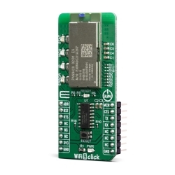
MIKROE WiFi 11 Click
MIKROE WiFi 11 Click is a compact add-on board that contains a WiFi and Bluetooth module that has dual bands for WiFi communication.
Product Overview
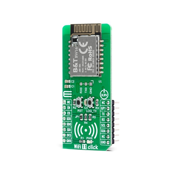
MIKROE WiFi 11 Click is a compact add-on board that contains a WiFi and Bluetooth module that has dual bands for WiFi communication. This board features the BW16, a low-power dual bands Wireless LAN (WLAN) and Bluetooth Low Energy SoC module from Ai-Thinker. This module supports the WiFi 5G and Bluetooth Low Energy 5.0, it consists of a high-performance MCU on a module named KM4, a low power MCU named KM0, WLAN (802.11 a/b/g/n) MAC, a 1T1R capable WLAN baseband, RF, Bluetooth, and peripherals. An inner antenna and many interfaces are available in this WiFi and Bluetooth module. This Click board™ is suitable for industrial wireless control, Bluetooth gateway, security ID tags, smart home applications, and many more.
WiFi 11 Click is based on the BW16, a low-power dual bands Wireless LAN (WLAN) and Bluetooth Low Energy SoC module from Ai-Thinker. The BW16 module represents a highly integrated Wi-Fi and Bluetooth SOC based on the RTL8720DN, a highly integrated Single-Chip with a low power dual bands (2.4GHz and 5GHz), Wireless LAN (WLAN), and Bluetooth Low Energy (v5.0). It consists of a high-performance MCU (ARM V8M, Cortex-M4F instruction compatible) named KM4, a low power MCU (ARM V8M, Cortex-M0 instruction compatible) named KM0, WLAN (802.11 a/b/g/n) MAC, a 1T1R capable WLAN baseband, RF, Bluetooth, and other peripherals. The BW16 integrates internal memories for complete WIFI and BLE 5.0 protocol functions. The embedded memory configuration also provides simple application developments.
WiFi 11 Click communicates with MCU using the UART interface at 57600 bps as its default communication protocol, but it is also left the option for the user to use other interfaces such as SPI and I2C if he wants to configure the module and write the library by himself. There is also a jumper JP1 on this Click board™ that enables the necessary pull-up resistors on the SCL and SDA lines of I2C communication.
NOTE: After primary module initialization, and before any program uploading, user should write network parameters and TCP server parameters.
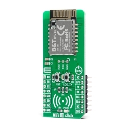
Additional functionality such as the Chip Enable button labeled as RST, which is used to Enable or put the module in Shut-Down mode, is provided and routed at EN pin of the mikroBUS™ socket. Alongside this pin, this Click board™ has one general purpose pin GP1 routed at the INT pin of the mikroBUS™ socket, which can be used in various cases like interrupt or some other purposes. WiFi 11 Click also has an additional header with UART RX0 and TX0 module pins on itself together with a button labeled as LOG_TX which can be used for Firmware Update or as low-power mode Wake-Up function.
This Click board™ is designed to be operated only with a 3.3V logic voltage level. A proper logic voltage level conversion should be performed before the Click board™ is used with MCUs with different logic levels. However, the Click board™ comes equipped with a library that contains easy to use functions and a usage example that may be used as a reference for further development.
Features & Specs
- Interface: I2C, SPI, UART
- Compatibility: mikroBUS™
- Dimensions: 57.15 x 25.4mm
- Input Voltage: 3.3V
- Frequency Range: Min. 2.412/5.180GHz, Max. 2.484/5.825GHz
- Receiver Sensitivity: -92dBm
- Transmit Power: 7±2dBm
- Operating Temperature Range: Min. -20°C, Max. +85°C
Documentation
Customer Reviews
Stock and Customer Discounts
Available Discounts
- $28.45 | 25+ units
- $26.96 | 100+ units