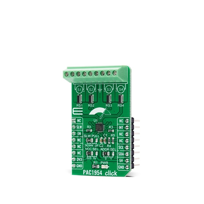
MIKROE PAC1954 Click
PAC1954 Click is a compact add-on board that contains an energy monitoring solution.
Product Overview
PAC1954 Click is a compact add-on board that contains an energy monitoring solution. This board features the PAC1954, a four-channel DC power/energy monitor from Microchip Technology. It uses real-time calibration to minimize offset and gain errors with no input filters required for this device. One major feature of the PAC1954 design is a set of digital comparators that allows the user to detect over/under voltage, over/undercurrent, and overpower against user-programmed limits for each channel and generate an alert when the threshold is exceeded. This Click board™ performs power calculations and energy accumulation, enabling energy monitoring with integration periods up to one year or longer.
PAC1954 Click is supported by a mikroSDK compliant library, which includes functions that simplify software development.
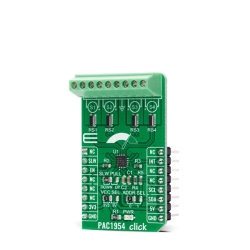
PAC1954 Click as its foundation uses the PAC1954, a four-channel energy monitoring solution with bus voltage monitors and current sense amplifiers that feed high-resolution ADCs from Microchip Technology. Its real-time calibration minimizes offset and gain errors. Built-in 8x averaging feature makes low noise high-resolution measurement results. There are four current sense shunt resistors connected to PAC1954’s integrated current sense amplifier. Electricity is brought to shunts via screw terminals where the middle screw connector represents GND used for bus voltage monitoring. Bus voltage, sense resistor voltage, and accumulated proportional power are stored in registers for retrieval by the MCU.
One major feature of the PAC1954 design is a set of digital comparators that allows the user to detect over/under voltage, over/undercurrent, and overpower against user-programmed limits for each channel and generate an alert when the threshold is exceeded. Digital circuitry of the PAC1954 performs power calculations and energy accumulation, which enables energy monitoring with integration periods up to one year or longer. After the Start-Up sequence, the PAC1954 is in the Active state and begins sampling the inputs sequentially. Voltage and current are sampled for all active channels at 1024 samples/second by default, and power is calculated and accumulated.
PAC1954 Click communicates with MCU using the standard I2C 2-Wire interface to read data and configure settings, supporting Fast Mode operation with a clock frequency up to 1MHz. Besides, it also allows the choice of the least significant bit of its I2C peripheral address by positioning the SMD jumper labeled as ADDR SEL to an appropriate position marked as 0 and 1. The Power-Down pin, labeled as EN and routed to the CS pin of the mikroBUS™ socket, optimizes power consumption and is used for power on/off purposes. All circuits, including the interface pins, are inactive in this state, and the PAC1954 is in the form of minimum power dissipation.
The SLW pin, routed to the RST pin of the mikroBUS™ socket, serves as the conversion rate control. If the SLW pin is asserted, the sample rate is eight samples per second. For sampling rates lower than 1024 samples/second, the PAC1954 is in a Sleep mode for a portion of the conversion cycle, which results in lower power dissipation. No matter the programmed sample rate, this new sample rate will affect the following conversion cycle.
The alert functionality, routed to the INT pin of the mikroBUS™ socket, has multiple purposes; to notify the system that a conversion cycle for all active channels is complete, or to notify the system that the accumulator or accumulator count has overflowed, or that an electrical parameter is outside the programmed limit. Besides the INT pin, the SLW pin can function as another alert feature by attaching a pull-up resistor to it, which is done via onboard SMD jumper labeled as SLW PULL by positioning 10k resistor to an appropriate position marked as DOWN or UP.
This Click board™ can operate with both 3.3V and 5V logic voltage levels selected via the VCC SEL jumper. This way, it is allowed for both 3.3V and 5V capable MCUs to use the I2C communication lines properly. However, the Click board™ comes equipped with a library containing easy-to-use functions and an example code that can be used, as a reference, for further development.
Features & Specs
- Interface: I2C
- Compatibility: mikroBUS™
- Dimensions: 42.9 x 25.4mm
- Input Voltage: 3.3V or 5V
- Supply Voltage: Min. 3.3V, Max. 5V
- Analog Input Voltage Range: Min. 0V, Max. 32V
- ADC Data Resolution: 16 bits
- Operating Temperature Range: Min. -40°C, Typ. +25°C, Max. +125°C
Documentation
Customer Reviews
Stock and Customer Discounts
Available Discounts
- $23.70 | 25+ units
- $22.46 | 100+ units