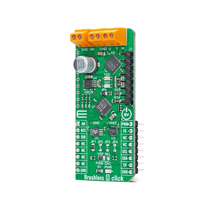
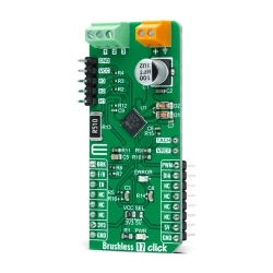
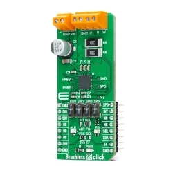
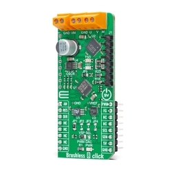
MIKROE Brushless 8 Click
Brushless 8 Click is a compact add-on board suitable for controlling BLDC motors with any MCU.
Product Overview
Brushless 8 Click is a compact add-on board suitable for controlling BLDC motors with any MCU. This board features the TC78B042FTG, a sine-wave PWM drive three-phase full-wave brushless motor controller from Toshiba Semiconductor. The TC78B042FTG has Toshiba’s original automatic phase adjustment function, which secures both a high-efficiency fan motor drive and sine-wave drive that reduces noise at a wide range of motor rotation speeds, from almost 0rpm (rotations per minute) at Start-Up up to several thousand rpm. This Click board™ makes the perfect solution for use in home appliances such as air-conditioner fans, air purifiers, and industrial equipment.
Brushless 8 Click is supported by a mikroSDK compliant library, which includes functions that simplify software development.
Brushless 8 Click is based on the TC78B042FTG, a three-phase brushless motor controller that offers high efficiency over a wide rotation range with automatic phase adjustment from Toshiba Semiconductor. This motor controller incorporates Toshiba’s original developed Intelligent Phase Control that secures high-level efficiency for a wide range of rotation speeds. As a result, the new devices can be used with motor drivers that have various voltages and current capacities as well as being used in combination with intelligent power devices at the output stages. It uses a sine-wave drive system with a smooth current waveform that reduces noise and generates less noise and vibration than motors with a rectangular wave drive system.
This Click board™ also contains a 3 channel Half-Bridge driver inverter, TB67Z800FTG from Toshiba Semiconductor, that receives its high and low side gate drive signals from TC78B042FTG and runs the connected Brushless DC Motor up to 22V/3A. The typical oscillation frequency is 9.22 MHz based on resistor R23 value 22kΩ drives the motor with 120° commutation. When the Hall signal indicates a rotation speed of 1 Hz or more, the motor rotates by estimating the rotor position according to the command of the LA pin. When rotation speed is less than 1Hz or the motor rotation direction is reversed, the motor is driven with 120° commutation.
The desired value on the previously mentioned LA pin as well as on other pins related to lead angle control, the TC78B042FTG obtains by the DAC3608, a low-power, eight-channel, digital-to-analog converter from Texas Instruments which establishes communication with MCU via I2C serial communication. Besides, the DAC43608 also allows the user to select a valid I2C address byte between 5V, GND, or I2C communication lines by positioning the jumper to an appropriate position marked from JP1 to JP4. As for the TC78B042FTG power supply, it is powered with a voltage value obtained by TPS7A49, an ultralow-noise linear regulator from Texas Instruments that converts an input value in the range of 6.5 to 22V to 6V that powers the main chip.
In addition to I2C communication, several GPIO pins connected to the mikroBUS™ socket pins are also used. The DIR pin, routed on the CS pin of the mikroBUS™ socket, is used to select the direction of motor rotation, while the control of the motor rotation speed itself can be chosen via the VSP SEL jumper. With this jumper, the user has the option of the rotation speed control using a PWM signal or using a value obtained by the DAC43608. The pin marked with RES routed at the RST pin of the mikroBUS™ socket can be used for Error detection more precisely for enabling or disabling commutation outputs. The FG pin at the INT pin of the mikroBUS™ socket represents the rotating pulse based on the selectable number of pulses per revolution. And the last pin labeled as AN provides accurate current monitoring via LT1999-10, a high-voltage, bidirectional current sense amplifier from Analog Devices.
There are also 2 headers on the board that contain both W, V, and U-phase Hall input signals, as well as a header with High & Low-side commutation signals. Besides, it has 2 LED indicators labeled as ISD and TSD intended for thermal shutdown and over-current protection.
This Click board™ is designed to be operated only with a 5V logic voltage level. A proper logic voltage level conversion should be performed before the Click board™ is used with MCUs with different logic levels.


Features & Specs
- Interface: Analog, GPIO, I2C, PWM
- Compatibility: mikroBUS™
- Dimensions: 57.15 x 25.4mm
- Input Voltage: 5V
- Supply Voltage: Min. 6.5V, Max. 22V
- Maximum Output Voltage: 18V
- Maximum Output Current: 3A
- Operating Frequency: Min. 6.8MHz, Typ. 9.22MHz, Max. 15.5MHz
- Power Dissipation: 4.25W
- Operating Temperature Range: Min. -40°C, Max. +115°C
Customer Reviews
Stock and Customer Discounts
Available Discounts
- $35.10 | 25+ units
- $33.26 | 100+ units