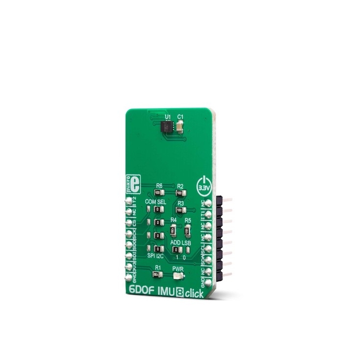
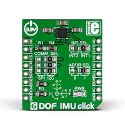
MIKROE 6DOF IMU 8 Click
6DOF IMU 8 Click is an advanced 6-axis motion tracking Click board™, which utilizes the ISM330DLC, a high-performance System in Package (SiP).
Product Overview
6DOF IMU 8 Click is an advanced 6-axis motion tracking Click board™, which utilizes the ISM330DLC, a high-performance System in Package (SiP), equipped with a 3-axis gyroscope, and a 3-axis accelerometer. A combination of the two most commonly used motion sensors allows for full 6D sensing. Tailored towards the Industry 4.0, the ISM330DLC is equipped with many smart features used to optimize the firmware and the power consumption. These features include a powerful interrupt engine capable of detecting several different events, 4K of FIFO buffer, configurable signal processing, and support for both I2C and SPI communication interfaces.
6DOF IMU 8 Click is supported by a mikroSDK compliant library, which includes functions that simplify software development.
The ISM330DLC is produced using well-proven microelectromechanical sensor (MEMS) manufacturing processes, along with the CMOS technologies that allow a high integration scale on a wafer level, providing good component matching and improved stability. These features allow 6DOF IMU 8 Click to be used for development of different types of motion-based applications, including industrial, IoT, and connected devices, robotics, drones, antenna alignment applications, optical image stabilization, and similar Industry 4.0 related applications.
6DOF IMU 8 Click is based on the ISM330DLC, a 3D accelerometer and 3D gyroscope with digital output for industrial applications, produced by STMicroelectronics. It is an advanced inertial module from iNEMO series, featuring an integrated microelectromechanical gyroscope and an accelerometer sensor (MEMS) within the same package. This device is designed with Industry 4.0 in mind, and produced using well-proven CMOS and MEMS fabrication processes, providing a high integration scale on a wafer level. This allows for a very good matching between the IC and the MEMS, offering very good robustness, mechanical shock immunity, and improved stability.
Three-axis gyroscope MEMS can be programmed to measure the rotation about each axis, in five different ranges of angular speed (degrees per angle, dps): ±125, ±250, ±500, ±1000, and ±2000. Three-axis accelerometer MEMS can be programmed to measure the acceleration along each axis, in four different acceleration ranges: ±2g, ±4g, ±8g, and ±16g. The developer can select an optimal range for both properties, depending on the application requirements.
The ISM330DLC incorporates a powerful programmable interrupt engine with two dedicated interrupt pins. The interrupt engine can detect many different events, including free-fall, wakeup, 6D orientation, tap, and double-tap events, activity and inactivity recognition, as well as a tilt detection with two configurable event detection options: an average window and an average threshold. The function of these two interrupt pins is not limited to these events. They can also be used for FIFO buffer-related events, such as a buffer is full, the buffer is empty, watermark level is reached, and the buffer is overrun. Data Ready event can also be signaled for each of the two sensors (gyro and accel). The INT 1 pin is routed to the mikroBUS™ INT pin, while the INT 2 pin is routed to the mikroBUS™ AN pin. These pins are labeled as IT1 and IT2 on the Click board™, respectively.
A FIFO buffer helps to reduce the communication bus traffic, processing load, and the power consumption, offering temporary storage for the output data. The ISM330DLC features a smart FIFO buffer with the capacity of 4096 bytes, which can be set to work in five different modes. The FIFO buffer is highly configurable. It is possible to select the data to be stored from several sources (gyroscope, accelerometer, timestamp, temperature…). As already discussed, the FIFO buffer itself can trigger interrupt for several events, alerting the host MCU about its status.
6DOF IMU 8 Click supports both SPI and I2C communication interfaces, allowing it to be used with a wide range of different MCUs. The communication interface can be selected by moving SMD jumpers grouped under the COM SEL to an appropriate position (SPI or I2C). The peripheral I2C address can also be configured by an SMD jumper when the Click board™ is operated in the I2C mode an SMD jumper labeled as ADD LSB is used to set the least significant bit (LSB) of the I2C address. When set to 1, the 7-bit I2C peripheral address becomes 0b1101011x. If set to 0, the address becomes 0b1101010x. The last digit (x) is the R/W bit.
This Click board™ uses both I2C and SPI communication interfaces. It is designed to be operated only with up to 3.3V logic levels. Proper conversion of logic voltage levels should be applied, before the Click board™ is used with MCUs operated at 5V.


Features & Specs
- Interface: I2C, SPI
- Compatibility: mikroBUS™
- Dimensions: 42.9 x 25.4mm
- Input Voltage: 3.3V
Documentation
Customer Reviews
Stock and Customer Discounts
Available Discounts
- $19.90 | 25+ units
- $18.86 | 100+ units