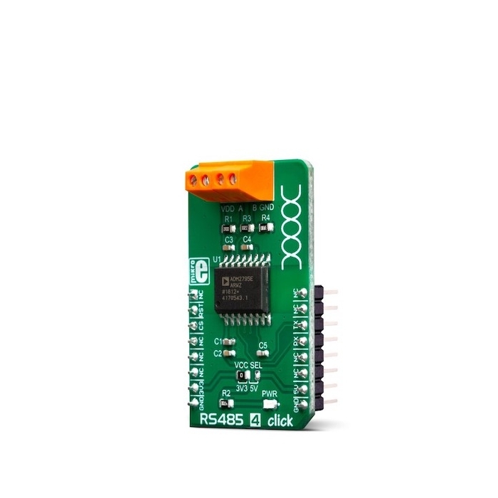
MIKROE RS485 4 Click
RS485 4 Click offers an UART to RS485 signal conversion, featuring the ADM2795E specialized IC with the complete galvanic isolation.
Product Overview
RS485 4 Click offers an UART to RS485 signal conversion, featuring the ADM2795E specialized IC with the complete galvanic isolation. Digital input and output signals are transmitted across the isolation barrier by using the ICoupler®, an IC scale transformer technology, which allows signals to be magnetically coupled across the isolation barrier within the IC, providing galvanic isolation for up to 5KV and data transfer rates up to 2.5Mbps. The ADM2795E is designed as a very robust and reliable UART to RS485 transceiver, allowing it to be used in very harsh industrial or other noisy environments.
RS485 4 Click is supported by a mikroSDK compliant library, which includes functions that simplify software development.
The ADM2795E, as the main component of the RS485 4 Click complies with many regulations: Level 4 EMC protection, IEC 61000-4-5 surge protection (±4kV), IEC 61000-4-4 electrical fast transient (EFT) protection (±2 kV), IEC 61000-4-2 electrostatic discharge (ESD) regulation… (the complete list can be found in the ADM2795E datasheet). In addition, it is protected of miswiring, featuring ±42V bus overvoltage protection. It can also operate with the extended bus voltage of ±25V, for the improved performance in very noisy conditions. Equipped with such a robust, reliable, and fast UART to RS485 signal converter, RS485 4 Click can be used in harsh industrial environments such as in stage DMX lighting, Remote Controller lines, etc.
RS485 is a serial communication standard, which is commonly used in several industries. It is a used in serial communication systems, supporting both full and half-duplex communication. RS485 standard uses balanced signaling, which is a good solution for noisy environments and longer bus lines. Also, it features somewhat larger signal levels compared to TTL logic levels used in the most embedded applications. Therefore, to allow communication over the RS485 bus, electronic components with TTL signal levels must use UART to RS485 signal converters, such as RS485 4 Click. On the other hand, the converter circuit should offer enough ESD protection to prevent damage of sensitive TTL electronic components, a requirement that RS485 4 Click satisfies in full.
The main active component of the RS485 4 Click is the ADM2795E, an integrated dual channel RS485 driver/receiver, with the ICoupler® isolation technology, made by Analog Devices. This integrated circuit features integrated galvanic isolation elements, providing the required isolation level. RS485 level signals are encoded into waveforms that are used to energize primary windings of the integrated transformers. At the secondary windings, the induced waveforms are decoded back into their original values and routed to the UART pins, with the appropriate TTL signal levels. The same working principle is applied in the opposite direction. This way, the digital signals are effectively conducted through the isolation barrier.
Output lines are internally routed through a set of transient filters, ESD suppressors, surge protection components, etc., replacing the complete set of commonly used external components (TVS diodes, TIPS®…). This reduces the number of reasonably expensive external protection components, cutting the time to market. There are also some other protections, such as miswiring protection, tolerance for up to ±42V on RS485 bus lines, etc.
RX and TX UART lines from the mikroBUS™ are routed to RXD and TXD pins of the ADM2795E. The CS pin of the mikroBUS™ is routed to the DE pin of the ADM2795E. It is used to activate the RS485 transmission driver. Similarly, RST pin of the mikroBUS™ is routed to the RE pin of the ADM2795E, and it is used to activate the receiver. Logic HIGH level on the DE pin activates the transmitter, and thus the UART TX session, while LOW logic level on the RE pin activates the receiver, and thus the UART RX session. The inverted logic on these pins is not a result of a random decision: they could be connected to a single point and driven by a single MCU pin: when there is a LOW level, the driver is disabled, while the receiver is enabled. This is not the case at this Click board™, as it is made for general use. However, in the case of most commonly used half-duplex communication topology, this can be very useful, reducing the number of required MCU pins.


Features & Specs
- Interface: UART
- Compatibility: mikroBUS™
- Dimensions: 42.9 x 25.4mm
- Input Voltage: 3.3V or 5V
- Receiver inputs voltage range: Min. -30V, Max. +30V
Customer Reviews

Stock and Customer Discounts
Available Discounts
- $37.95 | 25+ units
- $35.96 | 100+ units