
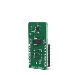
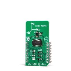
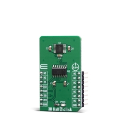
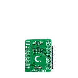
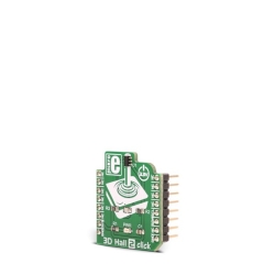
MIKROE 3D Hall 2 Click
3D Hall 2 Click is a very accurate magnetic field sensing Click board™, used to sense the magnetic field strength in three perpendicular axes.
Product Overview
3D Hall 2 Click is a very accurate magnetic field sensing Click board™, used to sense the magnetic field strength in three perpendicular axes. It relies on a TLV493D-A1B6, a low power 3D magnetic sensor from Infineon. This sensor has a separate Hall sensor for each axis, which allows a very reliable magnetic field sensing in 3D space, offering basis for accurate angle calculations. The TLV493D-A1B6 sensor uses industry standard I2C communication interface and requires a very low count of external components. The I2C interface is also used for the chip reset, so the sensor features a very low count of pins.
The sensor consumes a very low amount of current, featuring an additional low power mode, which allows even lower power consumption, which with its low count of pins, makes this sensor a perfect choice for various IoT applications. The internal Hall sensors are matched, making the Click board™ perfectly suited for development of various gaming applications (joystick), general control applications such as contactless knobs and potentiometers, or some other type of human interface device (HID) based on an accurate angle sensing.
3D Hall 2 Click carries the TLV493D-A1B6, a low power 3D magnetic sensor, from Infineon. This sensor relies on a Hall effect to accurately sense magnetic field changes on three perpendicular axes. The internal sensing elements are spinning Hall sensor plates, connected to a 12bit low noise Analog to Digital Converter (ADC), which sequentially samples each sensor, providing 12-bit spatial data over the I2C interface. An additional 8-bit thermal sensor is also available, and it is used for the thermal compensation.
The magnetic sensor has very low pin count (only 6), packed in a SOP6 casing. Therefore, the I2C interface is used for the reset too, while the interrupt pin is multiplexed with the I2C clock line. The interrupt is a useful feature which is used to signal a data ready event to the host microcontroller. For more robust data transfer, the device also contains a frame counter, which increases after each sensor sampling cycle. If the cycle was stopped for whatever reason, the frame counter will indicate this problem, and the application is able to take the necessary steps. Parity Error Check mechanism is also implemented for even more data transfer robustness.
Sensor provides raw data output, based on a strength of the magnetic field. The measurement is affected by many factors: slight manufacturing differences between ICs affect the readings, even the slight differences between Hall plates within the same IC might affect the accuracy, although the IC contains highly matched sensing elements. Also, the altitude might affect the readings, as well as temperature changes. Therefore, the sensor IC is equipped with the thermal sensor, used to measure influence of the ambient temperature. Unlike errors which occur as the result due to influence of other elements, the thermal influence is not linear and therefore, the host firmware should utilize a Look-up Table (LUT) for several thermal values, in order to achieve linear response. The thermal sensor allows reducing the error margin of the angle measurement from ±2˚ to ±3˚ by using such LUT table compensation. The datasheet contains the whole calibrating procedure, as well as the angle calculation based on raw sensor data, as well as formulas for conversion the thermal and the magnetic data.
There are two configuration registers, used to set the working parameters. The interrupt functionality, thermal sensor availability, the power mode, I2C interface speed, data parity test, and other working parameters are contained within two configuration registers, referred to as MOD1 and MOD2 in the datasheet. The I2C address of the device can be changed by overwriting corresponding I2C address bits in these two registers. The I2C peripheral address is additionally determined at the startup, by sampling the state of the SDA (I2C Serial Data) pin within first 200 µs, after which the address remains fixed until the next reset cycle. I2C pins (SCL and SDA) are routed to the mikroBUS™ of the Click board™ for an easy interfacing with the development system.
The Click board™ can operate with 3.3V MCUs only, and it is already equipped with the pull-up resistors. It is ready to be used as soon as it is inserted into a mikroBUS™ socket of the development system. The Click board™ comes supported by the library with the simple and easy to use functions, compatible with all the MikroElektronika compilers.


Features & Specs
- Interface: I2C
- Compatibility: mikroBUS™
- Dimensions: 28.6 x 25.4mm
- Input Voltage: 3.3V
Documentation
Customer Reviews
Stock and Customer Discounts
Available Discounts
- $14.20 | 25+ units
- $13.46 | 100+ units