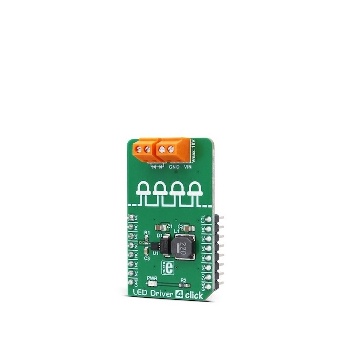
MIKROE LED Driver 4 Click
LED Driver 4 Click is a form of a high-efficiency boost converter that is ideally suited for driving an array of white LEDs.
Product Overview
LED Driver 4 Click is a form of a high-efficiency boost converter that is ideally suited for driving an array of white LEDs. The driver has the ability to dim the connected LED array, without producing any noise on the output. The Click board™ is capable of driving a LED array with up to 26V, providing a constant current to the LED segments. The LED segments are connected in series between the output terminals, which results in an even current distribution, thus providing a uniform brightness of each LED. A built-in soft-start function prevents large inrush current. Output open LED circuit, thermal, and undervoltage protection, provide a reliable operation.
The choice of the fixed internal switching frequency of the driver IC allows smaller components to be used on the Click board™. Apart from a small inductor and a Schottky diode, the driver IC requires only a few more components, such as the small sensing resistor, which determines the current through the LED array. The high switching efficiency, protection features, noiseless output, as well as the small footprint of this device, allow it to be used in various portable and battery powered applications, such as the cellular phones, portable media devices, backlighting for the media form factor displays, backlit keys on the computer keyboard, and similar applications that require a steady and reliable source of dimmable light.
The integrated circuit component used to drive a LED array on this Click board™, is the TPS61160A, a white LED driver with PWM brightness control, from Texas Instruments. The TPS61160A driver uses the boost converter topology, with the current mode control. Its operation is very similar to a typical boost DC-DC converter with some additional features, useful for LED array driving.
The Click board™ is able to provide up to 26V on the output terminals, after which, the open LED sensing section will shut down the output stage MOSFET and the IC itself, as a protection measure. This prevents the output voltage to exceed the maximum ratings of the device in the case when the output LED is disconnected. The same will happen if the voltage at the feedback pin drops under 50% of its nominal value, which is 200mV.
The TPS61160A allows PWM signal to be applied to its CTRL input, routed to the PWM pin of the mikroBUS™, which is labeled as CTL. Signal applied to this pin will modulate the feedback voltage on the FB pin, which after being filtered through the LP filter, reduces the DC current on the output and through the LED array. This dimming technique will not produce any noise, as the DC current is actually scaled down, while the PWM is applied only to the internal feedback voltage. For optimum performance, the PWM frequency should stay within the range of 5 kHz to 100 kHz.
The current through the LED segments is sensed via the onboard resistor connected between the GND and the FB pin. It is chosen so that the maximum current through the LEDs is 20 mA. This is optimal current for the white LEDs, providing the maximum brightness without LED deterioration. Note that while this is true for most of the white LEDs, the datasheet of the particular LEDs used with the LED Driver 4 Click should be checked for the forward current parameter. It should not be less than 20 mA. As explained above, the dimming function will reduce this current, resulting in dimmer LED light.
Soft-start function is built into the device and it slowly ramps the voltage at the FB pin, resulting with a slow increase of the output voltage, over a period of about 6 ms, preventing high inrush currents. Additionally, the internal current limit is set to half the maximum current specification for the first 5 ms of operation.
Applying LOW logic level to the CTL pin for more than 2.5 ms will put the device into the Shutdown mode. While in Shutdown mode, the current consumption is minimal. However, a current path still exists through the inductor and the Schottky diode. To prevent unwanted activation of the LED array, the minimum forward voltage of the LED array should be above the input voltage.
The power supply for the LED array is connected via the VIN screw terminal, allowing external power source to be used. The rating of the external power source should stay within the range of 2V to 18V. The second screw terminal with the LED icon underneath is used for connecting the LED array. The maximum forward voltage of the LED array should stay below minimum overprotection voltage of the device, which is typically 25V. The following formula can be applied to obtain the maximum number of LEDs allowed within the LED array:
->  <-
<-
Where:
- NLED = number of LED elements within the array
- VFLED(MAX) = maximum forward voltage of the single LED element
- VOVP = minimum overprotection voltage of the TPS61160A IC
The maximum forward voltage of the LED element depends on the used LED type. It can be found in the datasheet of the used LED. The minimum overprotection voltage of the TPS61160A IC can be found in the TPS61160A, but it is also available in the Electrical Characteristics table, below.
Click board™ itself is powered via 5V mikroBUS™ rail. However, the Click board™ allows both 3.3V and 5V MCUs to be used to drive its CTL input, as long as the voltage for the LOW logic level stays under 0.4V, and the voltage for the HIGH logic level applied to this pin, stays above 1.2V.
The use of the Led Driver 4 Click is easy and straight-forward. However, MikroElektronika provides a library that contains functions compatible with the MikroElektronika compilers, which can be used for simplified LED array driving. The library also contains an example application, which demonstrates their use. This example application can be used as a reference for custom designs.


Features & Specs
- Interface: PWM
- Compatibility: mikroBUS™
- Dimensions: 42.9 x 25.4mm
- Input Voltage: 5V
- Input Voltage (VIN terminal): Min. 2V, Max. 18V
- Overprotection Voltage (at the LED output terminal): Min. 25V, Typ. 26V, Max. 27V
- LED Element Current: 20mA
- Switching Frequency: Min. 500 kHz, Typ. 600 kHz, Max. 700 kHz
- Minimum Pulse Width at the CTL Input: 50ns
- The Frequency of the PWM Signal at the CTL Input: Min. 5 kHz, Max. 100 kHz
Documentation
Customer Reviews
