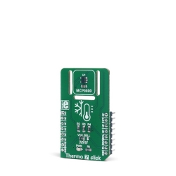
MIKROE Thermo 7 Click
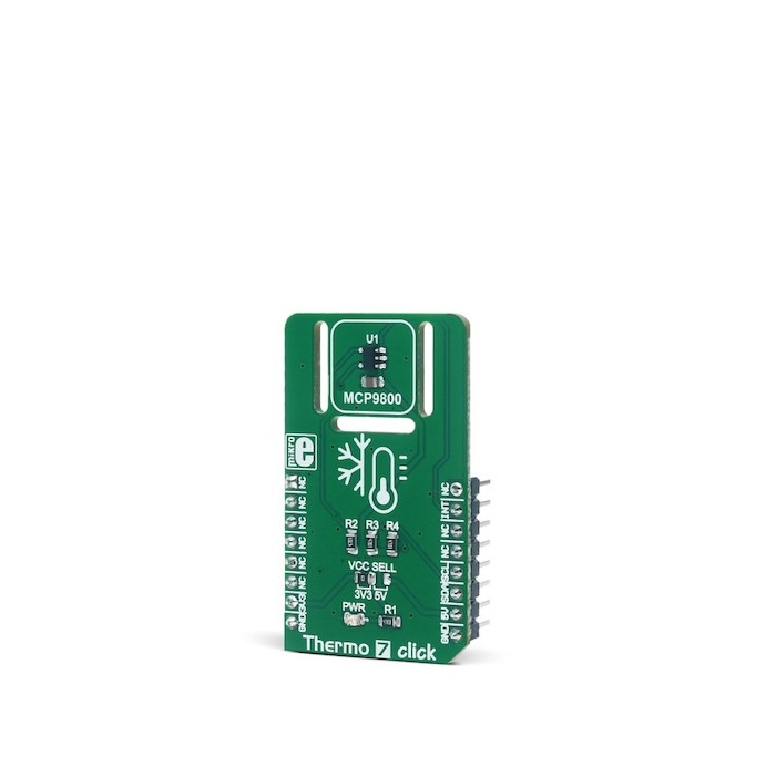
The active temperature sensing component on Thermo 7 Click is the MCP9800, a high accuracy temperature sensor IC with the 2-Wire interface, from Microchip.
Product Overview
Thermo 7 Click is a Click board™ equipped with the sensor IC, which can digitize temperature measurements between -55°C and +125°C so that the temperature measurement data can be processed by the host MCU. Thermo 7 Click provides an accuracy of ±1°C in the range from -10°C to +85°C. The sensor used on this Click board™ has a great combination of features that make it a perfect choice for any temperature measurement application: low power consumption, selectable sampling resolution, programmable interrupt engine, compact sensor size, alert output pin, and more. The sensor itself requires almost no external components, which simplifies the design, reducing the cost and cutting the time to market.
The Click board™ is specially designed so it retains the specified characteristics of the sensor IC. Equipped with this sophisticated, accurate and simple to use sensor IC, it can be used for measuring and monitoring the temperature in a whole range of applications, such as the PC case and other internal components temperature monitoring, office equipment and entertainment systems thermal monitoring, general purpose thermal measurement, and similar digital thermal measurement applications, that require a precise thermal measurement and an overtemperature alert.
The active temperature sensing component on Thermo 7 Click is the MCP9800, a high accuracy temperature sensor IC with the 2-Wire interface, from Microchip. The Click board™ itself has a reasonably small number of components because most of the measurement circuitry is already integrated on the MCP9800 sensor. The I2C / SMBus compatible serial interface lines, along with the ALERT pin, which also works in the open drain configuration, are pulled up by the onboard resistors. The 2-Wire lines are routed to the respective I2C lines of the mikroBUS™ (SCK and SDA), while the ALERT pin is routed to the INT pin of the mikroBUS™.
The sensor IC uses the I2C/SMBus compatible communication interface. There are four registers, used to set the temperature limit, temperature hysteresis for the interrupt events, configuration register used to store all the working parameters, and the read-only register which holds the sampled temperature data. More information about all the registers can be found in the MCP9800 datasheet. However, provided library contains functions that simplify the use of the Thermo 7 Click. The included application example demonstrates their functionality and it can be used as a reference for custom design.
An analog signal from the thermal sensor is sampled by the sigma-delta ADC converter, with the selectable resolution of 9, 10, 11 and 12 bits. The sampling resolution affects the temperature step sizes, as well as the time required to complete the conversion. The step sizes vary between the 0.5°C with 30ms of conversion time for 9bit sampling, and 0.0625°C with 240ms of conversion time for 12bit resolution. The selectable resolution allows a compromise to be made between the resolution and the conversion time, depending on the application requirements.
The ALERT pin is used to trigger an interrupt event on the host MCU. This pin has a programmable polarity: it can be set to be asserted either to a HIGH logic level or to a LOW logic level. Since the Click board™ features a pull-up resistor, it is advised to set the polarity so that the asserted state drives the pin to a LOW logic level. A special mechanism is employed to reduce false ALERT triggering. This mechanism includes queueing of the cycles in which the temperature limit is exceeded. As already described, the ALERT pin is routed to the INT pin of the mikroBUS™.
The ALERT pin can be set to work in two different modes: Comparator mode and Interrupt mode.
When working in the Comparator mode, this pin will be triggered whenever a temperature limit is exceeded. The ALERT pin stays asserted until the temperature drops below the hysteresis level. Both values are set in the respective temperature registers (limit and hysteresis). This mode is useful for thermostat-like applications: it can be used to power down a system in case of overheating or turn off the cooling fan if the temperature is low enough.
If set to work in the Interrupt mode, the ALERT pin will stay asserted after exceeding the temperature limit, until any internal register is read. When the temperature drops below the hysteresis level, the ALERT pin will be asserted again, waiting for the internal registers to be read once again. This mode is used to trigger an interrupt on the host MCU, which is supposed to read the sensor when the interrupt event is generated.
The device can be set to work in several different power modes. It can be set to continuously sample the temperature measurements, it can be set to work in the one-shot mode, and it can be set to stay in the shutdown mode. The shutdown mode consumes the least power, keeping all the internal sections but the communication section, unpowered. The one-shot mode allows the device to stay in the shutdown mode, run a single conversion cycle on demand, and the revert back to the shutdown mode. This allows for a lower power consumption.
The design of the Click board™ itself is such that the thermal radiation from other components, which might affect the environmental temperature readings of the sensor, is reduced. The onboard SMD jumper labeled as VCC SEL allows voltage selection for interfacing with both 3.3V and 5V MCUs.


Features & Specs
- Interface: I2C
- Compatibility: mikroBUS™
- Dimensions: 42.9 x 25.4mm
- Input Voltage: 3.3V or 5V
- Temperature Range (accuracy ±3˚C): Min. -55°C, Max. +125°C
- Temperature Range (accuracy ±1˚C): Min. -10°C, Max. 85°C
- Communication Speed: Min. 0 kHz, Max. 400 kHz
- Conversion Time (min 9bit, max 12bit): Min. 30ms, Max. 600ms
Documentation
Customer Reviews
Stock and Customer Discounts
Available Discounts
- $9.45 | 25+ units
- $8.96 | 100+ units