MIKROE Smart Sens Click
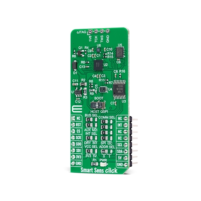
Smart Sens Click is a compact add-on board that contains an smart sensor system with an integrated IMU sensor.
Product Overview
Smart Sens Click is a compact add-on board that contains an smart sensor system with an integrated IMU sensor. This board utilizes the BHI260 and BMM150, an ultra-low-power programmable smart sensor and magnetometer from Bosch Sensortec. The BHI260 includes a programmable and powerful 32-bit MCU, a 6-axis IMU, and a robust software framework. In addition to its internal functions, it also performs signal data processing from the BMM150 that performs measurements of the magnetic field in three perpendicular axes. In addition to these primary functions, this Click board™ allows users to select the desired serial interface, use the debug interface, and select BOOT mode. This Click board™ represents an ideal solution for running always-on sensor data processing algorithms at the lowest power consumption.
Smart Sens Click is supported by a mikroSDK compliant library, which includes functions that simplify software development.
Smart Sens Click as its foundation uses the BHI260 and BMM150, a programmable smart sensor combining accelerometer, gyroscope, and fusion software alongside standalone geometric sensor from Bosch Sensortec. The BHI260 is based on the 32-bit microcontroller (Fuser2) and is mainly intended as a coprocessor offloading the main CPU from any sensor data processing-related tasks, in this case, data from BMM150. It integrates Inertial Measurement Unit (6DoF IMU) and Event-Driven Software Framework, making the BHI260 a complete sensor subsystem and computing platform for always-on sensor data processing algorithms at the lowest power consumption.
The BMM150 is a geomagnetic sensor that allows measurements of the magnetic field in three perpendicular axes. An application-specific circuit (ASIC) converts the output of the geomagnetic sensor to digital results, which is then sent to the BHI260 for signal processing over the industry-standard digital I2C interface. The BMM150 can communicate with the BHI260 in two ways, by choosing the main or auxiliary I2C controller interface. The selection can be made by positioning SMD jumpers labeled as BUS SEL to an appropriate position, AUX or M2I. Note that all the jumpers' positions must be on the same side, or the Click board™ may become unresponsive.
Four magnetometer-based interrupt engines are integrated into the BMM150: Low-Threshold, High-Threshold, Overflow, mapped to the INT pin of the BMM150, and Data Ready mapped to the DRY pin of BMM150. By positioning SMD jumpers labeled as INT SEL to an appropriate position (INT or DRY), the user chooses which interrupt will be forwarded to BHI260 and with which BHI260 will perform data processing by BMM150.
Smart Sens Click allows using both I2C and SPI interfaces to communicate with MCU. The selection can be made by positioning SMD jumpers labeled as COMM SEL to an appropriate position. Note that all the jumpers' positions must be on the same side, or the Click board™ may become unresponsive. While the I2C interface is selected, the BHI260 allows choosing the least significant bit (LSB) of its I2C peripheral address using the SMD jumper labeled ADDR SEL. In addition to interface pins, this Click board™ also uses a Reset pin, RST pin on the mikroBUS™ socket, and INT pin of the mikroBUS™ socket, which indicates the data transfer request from the BHI260 to the MCU.
Since the BHI260 and BMM150 for operation requires a 1.8V logic voltage level to work correctly, a small regulating LDO is used, the SPX3819, providing a 1.8V out of mikroBUS™ power rails. That's why voltage-level translators are also featured, the TXB0106 and PCA9306. The interface bus lines are routed to the dual bidirectional voltage-level translators, allowing this Click board™ to work with both 3.3V and 5V MCUs properly.
In addition, the onboard BOOT switch is used to select whether the host interface shall be used (HOST position) or whether the BHI260 shall attempt to boot from an onboard QSPI Flash memory, the W25Q32JW, and run in a Standalone operation mode (QSPI position). Besides, at the top of the Smart Sens Click, an additional unpopulated header is marked as cJTAG, which the user can use for debugging purposes, available through the JTAG interface pins (TCK and TMS).
This Click board™ can operate with both 3.3V and 5V logic voltage levels selected via the VCC SEL jumper. This way, it is allowed for both 3.3V and 5V capable MCUs to use the communication lines properly. However, the Click board™ comes equipped with a library containing easy-to-use functions and an example code that can be used, as a reference, for further development.


Features & Specs
- Interface: I2C, SPI
- Compatibility: mikroBUS™
- Dimensions: 57.15 x 25.4mm
- Input Voltage: 3.3V or 5V
- BHI260 Acceleration Range: Min. ±2g, Max. ±16g
- BHI260 Accelerometer Resolution: 16 bit
- BHI260 Accelerometer Sensitivity: Min. 16384 LSB/g, Max. 2048 LSB/g
- BHI260 Gyroscope Range: Min. 125°/s, Max. 2000°/s
- BHI260 Gyroscope Resolution: 16 bit
- BHI260 Gyroscope Sensitivity: Min. 16.4 LSB/°/s, Max. 262.4 LSB/°/s
- BMM150 Magnetometer Range (X, Y): ±1.3 mT
- BMM150 Magnetometer Range (Z): ±2.5 mT
- BMM150 Magnetometer Resolution: 13 bit
- Operating Temperature Range: Min. -40°C, Typ. +25°C, Max. +85°C
Documentation
Customer Reviews

Stock and Customer Discounts
Available Discounts
- $28.45 | 25+ units
- $26.96 | 100+ units