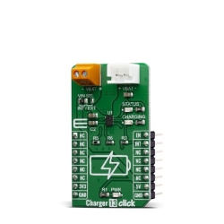
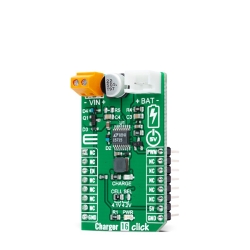
MIKROE Charger 18 Click
Charger 18 Click is a compact add-on board representing a single-cell battery charger.
Product Overview
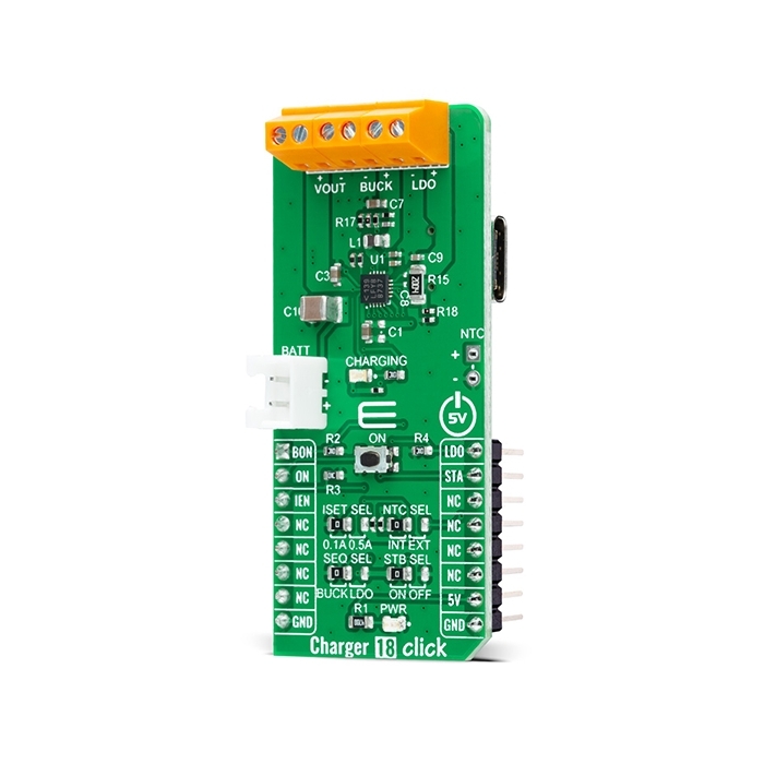
Charger 18 Click is a compact add-on board representing a single-cell battery charger. This board features the LTC3553, a micropower, highly integrated power management, and battery charger for single-cell Li-Ion/Polymer battery applications from Analog Devices. Designed specifically for USB applications, it also includes a PowerPath manager with automatic load prioritization and input current limit, a battery charger, and numerous internal protection features. It also indicates a battery charge state, and it comes with a synchronous 200mA buck regulator and a 150mA low dropout linear regulator (LDO). This Click board™ is suitable as a Li-Ion/Polymer battery charger for portable devices and accessories, power tools, and more.
Charger 18 Click is supported by a mikroSDK compliant library, which includes functions that simplify software development.
Charger 18 Click as its foundation uses the LTC3553, a micropower multifunction power management integrated circuit (PMIC) for portable Li-Ion/Polymer battery-based applications from Analog Devices. It combines a USB-compatible PowerPath manager with automatic load prioritization delivering up to 400mA battery charge current from a 5V USB input. The device’s ‘instant-on’ operation ensures immediate system load power when a USB supply is available, even with a fully discharged battery. Alongside a stand-alone battery charger, it also has a high-efficiency synchronous 200mA buck regulator and a 150mA low dropout linear regulator available on the present onboard connectors.
This Click board™ has an input current limit selection allowing the user to select between 100mA and 500mA input current limit. The choice can be made by positioning the SMD jumper labeled as ISET SEL to an appropriate position. Besides ISET, it also possesses SEQ SEL jumper selection determining which regulator is enabled before the other. The first-regulator power-up selection is made by positioning this SMD jumper to an appropriate position marked as BUCK or LDO.
On the other hand, the BON and LDO pins routed to the AN and PWM pins on the mikroBUS™ socket enable the buck and LDO regulators by setting these pins to a high logic state. Alongside these pins, the LTC3553 also includes a pushbutton input to control the two regulators and system reset - an onboard pushbutton labeled ON, also routed to the RST pin on the mikroBUS™, representing the Regulator Ignition button. Pressing the button causes an STA interrupt, informing the MCU that this event has occurred.
These regulators are also related to a Standby Mode, selectable through an SMD jumper labeled as ISET SEL. When this jumper is placed ON, the buck and the LDO regulator quiescent current are reduced to low levels while maintaining output voltage regulation. The buck regulator is limited to a 10mA maximum load current in this mode, and the LDO regulator’s response to line and load transients is slower.
As already mentioned in the text, this Click board™ communicates with MCU using several GPIO pins. With the IEN pin routed to the CS pin on the mikroBUS™ socket is pulled high, the LTC3553 enters Suspend mode to comply with the USB specification. In this mode, the power path between USB and VOUT is put in a high impedance state to reduce the USB input current. This Click board™ also comes with a blue LED labeled as CHARGING for battery charging state.
An NTC function is also available for temperature-qualified charging. The temperature monitoring feature is selectable via jumper labeled as NTC SEL, where the user can choose between external or internal modes of monitoring. A negative temperature coefficient (NTC) thermistor input for the battery temperature monitor is provided for external mode.
This Click board™ can be operated only with a 5V logic voltage level. The board must perform appropriate logic voltage level conversion before using MCUs with different logic levels. However, the Click board™ comes equipped with a library containing functions and an example code that can be used, as a reference, for further development.

Features & Specs
- Interface: GPIO
- Compatibility: mikroBUS™
- Dimensions: 57.15 x 25.4mm
- Input Voltage: 5V, External
- Supply Voltage: 5V
- Charge Output Current: 400mA
- Buck Regulator Output Current: 200mA
- LDO Output Current: 150mA
- Operating Temperature Range: Min. -40°C, Typ. +25°C, Max. +85°C
Documentation
Customer Reviews
Stock and Customer Discounts
Available Discounts
- $27.50 | 25+ units
- $26.06 | 100+ units