
MIKROE Brushless 23 Click
Brushless 23 Click is a compact add-on board suitable for controlling BLDC motors with any microcontroller.
Product Overview
Brushless 23 Click is a compact add-on board suitable for controlling BLDC motors with any microcontroller. This board features the TC78B011FTG, a three-phase sine-wave PWM pre-driver realized with six external MOSFETs to drive sensorless brushless motors from Toshiba Semiconductor. Some of the main features are a built-in closed-loop speed control function with internal non-volatile memory (NVM) for speed profile setting and the ability to set other features such as rotation direction selection, brake, Standby mode, and others. It also has a wide operating voltage range of 11V to 27V with an output current capacity of 5A and several built-in error detection circuits. This Click board™ provides optimum operational efficiency in applications such as high-velocity server fans, blowers, and pumps.
Brushless 23 Click is supported by a mikroSDK compliant library, which includes functions that simplify software development.
Brushless 23 Click is based on the TC78B011FTG, a three-phase sine-wave PWM pre-driver capable of driving Delta or Wye configured motors from Toshiba Semiconductor. Motor rotation is controlled without Hall sensors by detecting the rotational position from the induced voltage. The TC78B011FTG has a built-in closed-loop speed control function, which regulates and maintains the motor rotational speed under dynamic power fluctuations and load variations. This function has an internal non-volatile memory (NVM) for speed profile setting. The TC78B011FTG also has protection features such as thermal shutdown, under-voltage, over-current protection, lock detection, and more.
The TC78B011FTG possesses a speed control command that can control the motor's start, stop, and rotation speed. This signal type is determined by the position of an onboard SW2 switch and register setting, allowing the selection among PWM, analog voltage signal, and standard I2C 2-Wire interface to read data and configure settings with a maximum frequency of 400kHz. The TC78B011FTG also allows choosing its I2C peripheral address by positioning SMD switches labeled as SW3 and SW4 to an appropriate position. In the case of PWM signal or analog voltage signal, the TC78B011FTG is controlled through the mikroBUS™ PWM signal marked as SPD.
This Click board™ has several operational modes: Standby, Idle, Brake, and Error Mode. Standby mode is available to reduce the power consumption, controlled by the SBY pin routed to the CS pin of the mikroBUS™ socket, together with register settings. After Power-on, with the SBY pin disabled, the TC78B011FTG reads parameters from NVM and stores them in the registers. After that, IC goes to the Brake sequence and then moves to Idle mode. The brake function is controllable by a register setting or an onboard SW1 switch. The TC78B011FTG starts the motor by Start-Up sequence with the speed control command set. When an abnormal condition is detected, IC moves to Error mode and automatically restarts after restart time. In Error mode with Stop as a speed control command, the TC78B011FTG will move to Idle mode.
Alongside I2C communication, several signals connected to the mikroBUS™ socket pins are also used to forward the information to the MCU. The DIR pin, routed on the RST pin of the mikroBUS™ socket, is used to select the direction of motor rotation (clockwise/counterclockwise), while the CMO pin, routed on the AN pin of the mikroBUS™ socket, serves as the motor’s output current monitoring. Also, the TC78B011FTG provides selectable interrupts chosen via the INT SEL jumper routed on the INT pin of the mikroBUS™ socket by positioning the SMD jumper to an appropriate position marked as ALR od FG. The default position of this jumper is the FG position which serves as a rotation speed indicator, while the ALR position represents an abnormality detection feature. Both features have visual indicators; a red LED marked as ALR, and a blue LED labeled as FG.
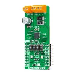
Brushless 23 Click is realized using six N-channel MOSFETs, the SSM6K513NU also from Toshiba Semiconductor, two for each of the three phases. Using these FETs, capable of handling 15A, allows low power dissipation when driving 5A BLDC before hitting the output current limit threshold, used to restrain the current flowing to the motor. It also supports an external power supply for the motor, which can be connected to the input terminal labeled as VM and should be within the range of 11V to 27V, while the BLDC motor coils can be connected to the terminals labeled as U, V, and W.
This Click board™ can operate with both 3.3V and 5V logic voltage levels selected via the VCC SEL jumper. This way, it is allowed for both 3.3V and 5V capable MCUs to use the communication lines properly. However, the Click board™ comes equipped with a library that contains easy-to-use functions and an example code that can be used, as a reference, for further development.


Features & Specs
- Interface: Analog, GPIO, I2C, PWM
- Compatibility: mikroBUS™
- Dimensions: 57.15 x 25.4mm
- Input Voltage: 3.3V or 5V, External
- Supply Voltage VCC: Min. 3.3V, Max. 5V
- External Supply Voltage VM: Min. 11V, Max. 27V
- Output Current: 5A
- PWM Frequency: Min. 1 kHz, Max. 100 kHz
- Operating Temperature Range: Min. -40°C, Typ. +25°C, Max. +105°C
Documentation
Customer Reviews
Stock and Customer Discounts
Available Discounts
- $23.70 | 25+ units
- $22.46 | 100+ units