Breakout Board for SD-MMC Cards

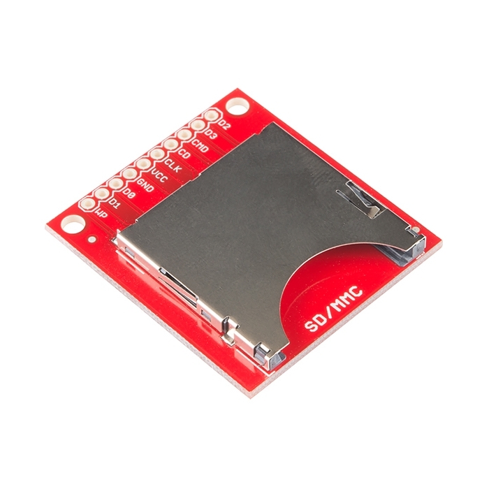
With SD and MMC memory prices dropping, the time is right for mass storage and datalogging. This breakout board will allow you to breakout the SD/MMC socket to a standard .1" 10-pin header. Perfect for breadboarding and the likes. Board comes fully assembled and tested as shown.

Replaces:BOB-00204

  • 1.3x1.5"

Breakout Board for SD-MMC Cards Product Help and Resources

Core Skill: Soldering

This skill defines how difficult the soldering is on a particular product. It might be a couple simple solder joints, or require special reflow tools.

1 Soldering

Skill Level: Noob - Some basic soldering is required, but it is limited to a just a few pins, basic through-hole soldering, and couple (if any) polarized components. A basic soldering iron is all you should need.
See all skill levels


Comments

Looking for answers to technical questions?

We welcome your comments and suggestions below. However, if you are looking for solutions to technical questions please see our Technical Assistance page.

  • I managed to get the SD reader working fine. The following works with ARDUINO UNO only

    The pins for other micro controllers such as ARDUINO MICRO are different (see ref section below)

    Pin 10 on Arduino should connect to D3 on the SD which is CHIP SELECT, via a potential divider. You need a potential divider because pin 10 gives out 5V and D3 can only accept 3.3V. I used three resistors for the potential divider - 4.7K, 1K and 220 ohms in series , with 4.7K attached to ground and 220 ohm attached to pin 10, tapping off 3.4V at the junction of 4.7K and 1K.

    Pin 11 on Arduino should connect to CMD on the SD which is DATA IN, via a potential divider. You need a potential divider because pin 11 gives out 5V and CMD can only accept 3.3V. I used three resistors for the potential divider - 4.7K, 1K and 220 ohms in series , with 4.7K attached to ground and 220 ohm attached to pin 11, tapping off 3.4V at the junction of 4.7K and 1K

    Pin 12 on the arduino should be connected DIRECTLY to D0 on the SD which is DATAOUT. No need for a potential divider here. D0 gives out 3.3V which is interpreted by arduino as HIGH, so no need for a potential divider.

    Pin 13 on Arduino should connect to CLK on the SD which is CLOCK via a potential divider. You need a potential divider because pin 13 gives out 5V and CLK can only accept 3.3V. I used three resistors for the potential divider - 4.7K, 1K and 220 ohms in series , with 4.7K attached to ground and 220 ohm attached to pin 13 tapping off 3.4V at the junction of 4.7K and 1K

    CD on the SD should be connected to Ground

    GND on the SD should be connected to Ground.

    VCC on the SD should be connected directly to 3.3V power pin on the Arduino

    D1, D2 and WP on the SD do not need to be connected to anything.

    NOTE: when writing to the sd card, you must use a file name with less than 6 characters, otherwise the chip does not record it, e.g. log.txt is good, but temperature.txt is too long.

    TUTORIALS

    Here are some tutorials that I found very useful

    1. http://www.martin-gardner.co.uk/how-to-connect-your-old-sd-card-to-an-arduino/

    2. http://www.ppl-pilot.com/logger/

    **3. **playground.arduino.cc/Learning/SDMMC

    I particularly liked http://www.martin-gardner.co.uk/how-to-connect-your-old-sd-card-to-an-arduino/ which shows exactly how to wire up the potential dividers.

    CONNECTING TO AN ARDUINO MICRO You will need to use the pin layout for the Micro which is different from the Uno. See here - http://www.codingcolor.com/microcontrollers/arduino-micro-wired-up-to-an-adafruit-microsd-card-breakout-board/

    Note that the MICRO has a dedicated clock pin, so CLK on the SD should connect to SLK on the MICRO, instead of pin 13 on the micro. Connection is via a potential divider as with the UNO. The MICRO has a dedicated MOSI pin, so CMD on the SD should connect to MOSI on the MICRO, instead of pin 11 on the MICRO. Connection is via a potential divider as with the UNO. The MICRO has a dedicated MISO pin, so D0 on the SD should connect to MISO on the MICRO, instead of pin 12 on the MICRO. Connection is direct - no potential divider needed.

    Pin 10 on the MICRO still connects to D3 on the SD via a potential divider. CS and GND pins on the SD are connected to GROUND VCC on the SD connects to the 3.3V pin on the MICRO

    Regards

    Craig Paardekooper

  • lylehaze / about 10 years ago / 1

    I have this board in a project, and have never been able to make it work. Using "tested" software that works for others, connections double (and triple) checked.

    The driver can not mount the card at all. I am wired for 4 bit (six wire plus power and ground) comms.

    After reading the comments.. is there some error in the board wiring or labeling? Maybe I'll drop back to 2 wire mode and see if that works any better.

    Thanks, Lyle

  • Member #186381 / about 10 years ago / 1

    this board is hopeless... CLK goes to nowhere and so the card never initializes!! it should go to #5 of the socket (pictured in datasheet) but it doesn't.

  • Member #442322 / about 10 years ago * / 1

    I made a Fritzing part for this product.

    Enjoy ! ;)

  • TimDC / about 11 years ago * / 1

    If ever there were a Sparkfun product that needed a hookup guide, this would be it.

  • Member #251154 / about 11 years ago / 1

    I think this is how the pins are assigned: 1) WP 2) DAT1 = IRQ 3) DAT0 = DOUT 4) GND 5) Vcc = 3.3V 6) CLK = SCLK 7) CD 8) CMD = DIN 9) CD/DAT3 10) DAT2 = RW only pin 3 (DAT0 = Dout), pin 6 (CLK=SCLK), pin 8 (CMD = Din), pin 9 (CD/DAT3 = CS) aside from Vcc and gnd are needed. Provide pull up resistor of around 10K for pins 3, 6, 8, and 9.

  • Lennart / about 11 years ago * / 1

    Hey, Sparkfun!

    Can we get a once-and-for-all statement regarding the wiring? Assume I am using an Uno, 5V (I'm not but let's talk pins instead of acronyms just to avoid further confusion), here are my questions:

    Which pin on this board do I connect to Uno's pin 13?

    Which pin on this board do I connect to Uno's pin 12?

    Which pin on this board do I connect to Uno's pin 11?

    Which pin on this board do I connect to the Uno pin I have nominated to be CS? I'm using pin 4.

    Which of these pins 4, 11, 12, 13 require level shifting?

    • Soldanr / about 11 years ago * / 1

      GOT IT!! On the UNO: CS = Arduino pin 10 = D3 on PCB | MOSI = Arduino pin 11 = CMD on PCB | SCK = Arduino pin 13 = CLK on PCB | MISO = Arduino pin 12 = D0 on PCB

      According to schematic pin 12, MISO, does not need any level shifting, connect direct to Arduino. I am using a MC14050BCPG level shifter to put out the 3.3V. Arduino 1.0.5 with SD.h library

  • Member #21083 / about 12 years ago / 1

    It's unfortunate that this breakout board doesn't have logic level converters on it so it can be used with +5V microcontrollers. I'll not be purchasing this board therefore.

    • Member #364496 / about 11 years ago / 1

      If this is really what you want then you should look on ebay where you can find what you want for less money than this.

      However I think it's very fortunate that this board doesn't have any extraneous parts and that is why I am purchasing this product.

      • carlmal / about 11 years ago / 1

        I think both of you are correct. I bought it, then it struck me, "I betcha it's 3.3V"...

  • Member #374613 / about 12 years ago / 1

    kglad1's "schematic" works great if you're curious about how to wire this to your Arduino. Just remember when using a Mega the SPI pins are not the same.

    pin 13 or 52 Mega pin 12 or 50 Mega pin 11 or 51 Mega pin 10 or 53 Mega

  • kglad1 / about 12 years ago / 1

    I have been able to get the older version of this card working with an Arduino reading and writing data. The new breakout board does not have a connection labeled CS. After reading the forum one person suggested that D3 is the SPI CS line on the breakout board. On the schematic pin one is CD/D3. On the Breakout board pin one is labeled D2. I tried using D2 as the CS line and D3 (pin 2 on the breakout board and labeld as CMD in the schematic) and still could not get the Arduino to recognized an SD card that is recognized on the earlier breakout board. What is the relationship top the labeled pins on board to the schematic? Does CD and D2 which is the first pin need to be connected somehow? Which pin on the board functions as CS line? I appreciate any clarification on this. I am using the following wiring/Fritzing diagram. http://garagelab.com/profiles/blogs/tutorial-how-to-use-sd-card-with-arduino. Thanks.

    • kglad1 / about 12 years ago / 2

      I got it to work. Here are the connections if using SdFat library. The above comments make more sense now :).

      D2 nothing

      D3 Chip Select line (CS) needs pull down resistors

      CMD pin 11, no pull down resistors

      CD nothing

      CLK clock connect to pin 13, needs pull down resistors

      VCC 3.3V

      GND ground

      D0 pin 12, needs pull down resistors

      D1 nothing

      WP nothing

      • Member #404913 / about 12 years ago / 1

        If I'm correct, as the Arduino pins outputs 5V and the MMC/SD card needs to be operated at about 3.4V, MISO does not need a voltage divider, while MOSI does. According with the connections scheme you suggest, CMD/PIN 11 is MISO (it doesn't need pull down resistor) and D0/PIN 12 is MOSI (and thus it needs the pull down resistor)?

  • makeder / about 12 years ago * / 1

    i have the same question about wiring- also which pin can be used for CS? i have tried wiring according to this: http://arduino.cc/playground/Learning/SDMMC with D0 as MISO and CMD as MOSI and CD as CS

    • brcox0789 / about 12 years ago / 1

      Yes, that is correct, I am using the same scheme although I haven't tested it on the new board yet. I'm assuming WP stands for write protection, but not sure what to connect to that pin if I am not using it. The datasheet says to put pull-up resistors on any unused connections namely D1 and D2.

      • brcox0789 / about 12 years ago * / 1

        Apparently the D3 pin needs to be used for the SPI CS line.

  • Member #130058 / about 12 years ago / 1

    How to wire this so the card is recognized and noted as not write protected, the pins listed as MISO and MOSI are not noted to any of the specific data pins.

    Perhaps my inexperience with these is the problem, but the drawings could note if multiple pins can be data in and out.

  • Jon Mayer / about 12 years ago / 1

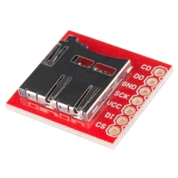
    Replacement: BOB-11403. We've revised this board to fit a new SD card socket, it has stayed the same otherwise.

Customer Reviews

No reviews yet.