- Home
- Product Categories
- Sensors
- Triple-Axis Digital-Output Gyro ITG-3200 Breakout

Triple-Axis Digital-Output Gyro ITG-3200 Breakout
Replacement:SEN-11977. We have a new rev of this breakout, go check it out! This page is for reference only.
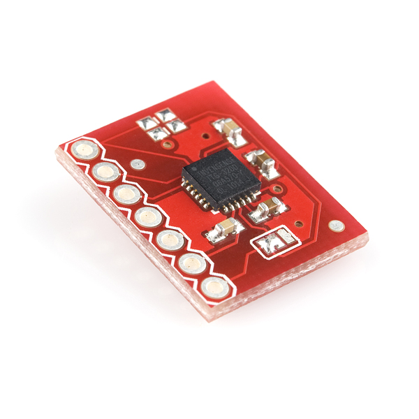
This is a breakout board for InvenSense's ITG-3200, a groundbreaking triple-axis, digital output MEMS gyroscope. The ITG-3200 features three 16-bit analog-to-digital converters (ADCs) for digitizing the gyro outputs, a user-selectable internal low-pass filter bandwidth, and a Fast-Mode I2C (400kHz) interface. Additional features include an embedded temperature sensor and a 2% accurate internal oscillator.
The ITG-3200 can be powered at anywhere between 2.1 and 3.6V. For power supply flexibility, the ITG-3200 has a separate VLOGIC reference pin (labeled VIO), in addition to its analog supply pin (VDD) which sets the logic levels of its serial interface. The VLOGIC voltage may be anywhere from 1.71V min to VDD max. For general use, VLOGIC can be tied to VCC. The normal operating current of the sensor is just 6.5mA.
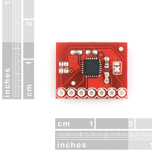
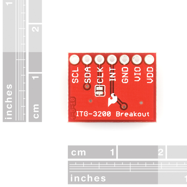
Communication with the ITG-3200 is achieved over a two-wire (I2C) interface. The sensor also features a interrupt output, and an optional clock input. A jumper on the top of the board allows you to easily select the I2C address, by pulling the AD0 pin to either VCC or GND; the board is shipped with this jumper tied to VCC. If you don't plan on using the CLKIN pin, you can short the jumper on the bottom of the board to tie it to GND.
This breakout board is shipped as shown in the images. Note that there are two unpopulated resistors on the I2C lines, these can be added later by the customer if desired.
Not sure which gyro is right for you? Our Accelerometer and Gyro Buying Guide might help!
- Digital-output X-, Y-, and Z-Axis angular rate sensors (gyros) on one integrated circuit
- Digitally-programmable low-pass filter
- Low 6.5mA operating current consumption for long battery life
- Wide VDD supply voltage range of 2.1V to 3.6V
- Standby current: 5μA
- Digital-output temperature sensor
- Fast Mode I2C (400kHz) serial interface
- Optional external clock inputs of 32.768kHz or 19.2MHz to synchronize with system clock
- Pins broken out to a breadboard friendly 7-pin 0.1" pitch header
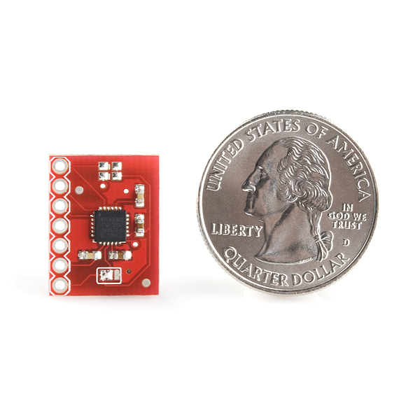
- 0.70 x 0.55" (17.78 x 13.97mm)
Triple-Axis Digital-Output Gyro ITG-3200 Breakout Product Help and Resources
Core Skill: Soldering
This skill defines how difficult the soldering is on a particular product. It might be a couple simple solder joints, or require special reflow tools.
Skill Level: Noob - Some basic soldering is required, but it is limited to a just a few pins, basic through-hole soldering, and couple (if any) polarized components. A basic soldering iron is all you should need.
See all skill levels
Core Skill: Programming
If a board needs code or communicates somehow, you're going to need to know how to program or interface with it. The programming skill is all about communication and code.
Skill Level: Competent - The toolchain for programming is a bit more complex and will examples may not be explicitly provided for you. You will be required to have a fundamental knowledge of programming and be required to provide your own code. You may need to modify existing libraries or code to work with your specific hardware. Sensor and hardware interfaces will be SPI or I2C.
See all skill levels
Core Skill: Electrical Prototyping
If it requires power, you need to know how much, what all the pins do, and how to hook it up. You may need to reference datasheets, schematics, and know the ins and outs of electronics.
Skill Level: Rookie - You may be required to know a bit more about the component, such as orientation, or how to hook it up, in addition to power requirements. You will need to understand polarized components.
See all skill levels
Comments
Looking for answers to technical questions?
We welcome your comments and suggestions below. However, if you are looking for solutions to technical questions please see our Technical Assistance page.
Customer Reviews
No reviews yet.
their is a single chip 3 axis acselerometer..
Home > Modern Device > Sensors > 3-Axis Accelerometer Module
so check it out whack em together using kicad for a full open source system.
I developed a simple-yet-comprehensive library for Arduino to use this sensor.
It contains two examples, one that basically just reads the axes and a more advanced one that uses the interrupt functionality of the ITG-3200.
You can find a feature list on the README file.
Source Code:
https://github.com/Cameri/Itglib
Direct Download:
https://github.com/Cameri/Itglib/zipball/master
thank you for this!
thanks for this! i'm attempting to adapt it to work on this sparkfun 9dof sensor board:
http://www.sparkfun.com/products/10125 and haven't quite figured it out. i edited your init function to perform the same register setup as the sparkfun test firmware, but haven't gotten anything out of the gyro yet.
any tips?
To get data out of the 9DOF board, you have to run the non-interrupt program, because that board doesn't break out the interrupt pins, and change the address from 0x69 to 0x68- the address pin is pulled on the 9 DOF i think.
I am having trouble finding two things on the datasheet; Does anyone knows the zero voltage of the gyro (the voltage the gyro normally outputs when it's not rotating) and the sensitivity measured in mV/deg/sec?
I am connecting ITG-3200 with Raspberry Pi. I got an error message while runing the SSH terminal. File "ITG-3200-4.py", line 87, in sensor.default_init() File “ITG-3200-4.py", line 73, in default_init self.sample_rate(0, 8) File "ITG-3200-4.py", line 66, in sample_rate self.bus.write_byte_data(self.addr, 0*15, div-1) IOError: [Errno 5] Input/output error
Thanks to:https://github.com/beli-sk/IMU_sensors/blob/master/itg3200.py
Please help me. Thank you so much.
i'm new to this sensor application....how do i get readings for x-axis..is it important to know about I2C..im not using arduino..but sk-40c kit which using PIC16F877A...
Hey guys... im using MAC OSX and Arduino UNO with this Gyro. Im using the code given above for testing. Everything seemed to have compiled. However when it comes to reading values what terminal program should I use? and how? Im new to Arduino. Justing playing around with this.
You can just use the Arduino Serial monitor to see the gyro in operation. After that you can write utilities with many scripting languages to monitor the output. I happen to use Python and the Python PyPlot to capture and analyze the data returns.
When i write initialization words it's going well (show i2c signals on oscilloscope). But when i try to read from ITG3200 it doesn't work. Because it always send back "who am i" register value 0xd2. What's wrong with it. help me...
Wow price gouging! 10.00 dollar chip in single quantities. Thanks for that SparkFun !! must be some magic resistors and capacitors for forty dollars. Care to explain SparkFun?
Yes, the IC can be bought separately. If you want, you can download the Eagle files and use BatchPCB to roll your own board. For $40, we designed the board, stock the associated components, reflow everything (SMD isn't the easiest to do with a hand-held soldering iron), test it, and send it on its way.
$30 extra bucks for the board, some components, and the time and effort to put it together. If it's not worth it to you, the files are up top, roll your own the way you want!
The PRT-10968 is $5.95 it has the same parts count and more design considerations. This makes no sense. I do appreciate the reply.
Those parts are also a LOT cheaper. Several times so.
I think you missed the point. PRT-10968 is roughly the same size, has many more components, and costs $5.95. The ICs may be cheaper, but you listed all of the things that supposedly justify an extra $30 for the product on this page that would also apply to PRT-10968, but obviously don't for some reason. "Designed the board" - the design of this board probably took 20 minutes. It's basically a bunch of escape routes to a 0.1" header and a few capacitors that are laid out exactly the way the datasheet specifies. Design not found.
I've been selling a similar device for $20 and I'm making a huge profit. $50 for this breakout is an unbelievable gouge. Sometimes you guys are pretty arrogant with your pricing. Just because you have a well known presence doesn't mean you need to rip people off. There are too many products on your website with similar price-gouging to even bother trying to list them all. You guys do good work, but this is just wrong.
Yeap http://www.hobbyking.com/hobbyking/store/uh_viewitem.asp?idproduct=26859
Hi everyone ;
I have a ITG3200 and I am controlling it a with PIC 16F877a. But I have a problem. I don't read data it. I am using mikroC and I am using I2C protocol. Written program that ;
void main(){ int X; TRISB=0; PORTB=0; TRISC=0xFF; PORTC=0; while(1){ I2C_Init(400000); I2C_Start(); I2C_Wr(0xD2); I2C_Wr(0x3E); I2C_Wr(0x80); I2C_Stop();
Delay_ms(100);
I2C_Start(); I2C_Wr(0xD2); I2C_Wr(0x00); I2C_Wr(0x69); I2C_Stop();
Delay_ms(100);
I2C_Start(); I2C_Wr(0xD2); I2C_Wr(0x16); I2C_Wr(0x18); I2C_Stop();
Delay_ms(100);
I2C_Start(); I2C_Wr(0xD2); I2C_Wr(0x3E); I2C_Wr(0x00); I2C_Stop();
Delay_ms(100);
I2C_Start(); I2C_Wr(0xD2); I2C_Wr(0x22); I2C_Repeated_Start(); I2C_Wr(0xD3); X = I2C_Rd(0u); PORTB=X; I2C_Stop(); } }
What's the problem this ? Can you help me ? please .. (S.O.S)
Are we need to use I2C voltage-level translator for connecting to arduino uno board.
I successfully used this MEMS gyro breakout ( with https://github.com/Cameri/Itglib) to create a fun musical synth prototype. Check it out here: http://www.youtube.com/watch?v=KiCoMHCS9Iw
Any body test the differece between L3G4200D and ITG3200?
Good product by Invense. However, unfortunately, all manufacturers speak about precision static conditions. In dynamics, Coriolis force principle for measurement rotation velocity produces accumulating errors. It would be nice if more information is provided for an end user when doing marketing. So additional efforts have to be spent to filter "bad" stuff in dynamics conditions like the following. This is what I was able to accomplish with this board: http://www.youtube.com/watch?v=pN-20mkjZxE
Label the axes please other it's just annoying.
Any encounter unable to set the Full Scale register bits?
I am sure my code is working properly, because I was able to set it.
Now I can't set DLPF_FS register, but I can still set all the other registers (INT_CFG, PWR_MGM...etc.) But I cannot set the Full Scale bits to 3.
the Quickstart link is broken
Hi all,
I just want to confirm if there is a very small typo in the DataSheet. Table 7 (page 22) states that Register 0 has the ID from bit 6 to bit 1. (bit 0 is not used). Doesn't the ID (which is 7 bit long) go from bit 6 to bit 0 (inclusive)????
Thanks.
If you read reg address 0 the device should respond 104d... Bit 0 (LSB) is hard coded to 0, if I am not mistaken. Depending on if you're reading or writing the MSB will change.
I would really like it if the pullup resistors were populated on the board. It would be much easier to depopulate them if unneeded than to try and add the surface mount resistors. I almost destroyed my board trying to put the surface mount resistors on. The schematic shows the resistors on the board.
Once I got all the resistors and jumpers set, the board worked well!
If I am using a PIC24 at 5V, do I need a level shifter to communicate with the ITG-3200???
thanks
Yes, you do.
The address of itg-3200 is no 0XD2, i think that is 0x69
No, it is actually 0xD2 for writing and 0xD3 for reading. The address if the ITG is 1101001b but the eighth bit tells if you are writing (0) or reading (1) so it becomes:
Writing: 1101001 0b = 0xD2
Reading: 1101001 1b = 0xD3
Hi,
I am having trouble connecting the gyro to a PIC24FJ256GA110. I have the following connections:
VIO: 1.84V
VDD: 3.3V
SCL, SDA: Two pull-up ressistor to 3.3V
CLK: to GND
INT: Floating
I am using the following code to run it:
define GYRO_MASTER 0x9000
define GYRO_BAUD_RATE 0x0027 // 100.00 kHz
//Initialize ITG3200 for experimentation
void gyro_Initialize(){
//Configure IO pins
GYRO_SCL_PORT = 0x0; // SCL3 is an input
GYRO_TRIS_SCL_PORT= 0x1; // SCL3 is an input
GYRO_SDA_PORT = 0x0; // SDA3 is an input
GYRO_TRIS_SDA_PORT = 0x1; // SDA3 is an input
OpenI2C3(GYRO_MASTER, GYRO_BAUD_RATE); //OPEN I2C3
return;
}
int gyro_read(int command){
int gyro_read;
StartI2C3(); //SEND START
IdleI2C3();
MasterWriteI2C3( 0xD2 ); // sends address to the itg3200 if pin 9 is held high (b1101001) 69,
//someone is 'avin a larf. Bit 8 is the r/w bit (low) THEREFORE D2
IdleI2C3();
MasterWriteI2C3( 0x0 ); //access device ID register. Bit 8 is the r/w bit (low)
RestartI2C3(); //SEND reSTART
IdleI2C3();
MasterWriteI2C3( 0xD3 ); //address device with r/w bit high as we want to read from the device THEREFORE D3
IdleI2C3();
//OS_Delay(10);
gyro_read = MasterReadI2C3(); //READ THE ADDRESS INTO THE ITG3200ID VARIABLE
IdleI2C3();
NotAckI2C3(); //SEND A NACK TO FINISH COMMS
IdleI2C3();
StopI2C3(); // stop all I2C communication
return gyro_read;
}
In the oscope I see the signal SCD and SCL sending the right address but I done get the ACK (instead of 0 in the 9th clock I get a 1). Finally, the answer I get from the gyro are all 1's (i.e. 255). Does anybody know what can be going on?
Thanks a lot.
If I am not mistaken, generally gyroscopes have an internal High pass filter not a low pass filter as specified in the features. Would it be that there is a misprint in the datasheet and on this site?
Thanks
Can gyros sense very small and precise tilt? Not full degree but arc-minute and even arc-seconds tilts?
Having problems getting ITG-3200 working with Arduino UNO (5V). Connected VDD and VIO to 3.3V, CLK and GND to Arduino GND, INT floating, SDA and SCL to A4 and A5, resp. No external pullups on SDA and SCL (I assumed the Arduino Wire Library uses the Atmega internal pullups). It appears that AD0 is set to 1, however just in case, I tried both addresses (0x68 and 0x69). I used the example code below, measured the SCL and SDA waveforms with a scope and for both addresses the bit patterns look valid. However, neither address is getting ACK'd by the gyro device during the ACK/NACK clock pulse. Can anybody out there advise?
void setup()
{
Wire.begin();
Serial.begin(9600);
}
void loop()
{
Wire.beginTransmission(0x69);
Wire.endTransmission();
Wire.beginTransmission(0x68);
Wire.endTransmission();
delay(500);
}
I had the same problem where the device would not respond to anything I sent it.
The data sheet says VLogic (VIO) voltage can be up to VDD. Wrong! You can't just tie them together.
To solve this I made a small voltage divider circuit with two 10k resistors in series between 3.3V and ground. I connected VIO to the junction between the two resistors (3.3V/2 = 1.65V) and now the gyro works every time.
It can be they just can't be tied together. VLogic needs to be powered up after VDD, that's all.
Hey,
Is there any chance it would be possible to purchase this board without the IC installed, to use it for another InvenSense product with a similar layout?
I know this is a very delayed response, but for products where we don't sell just the blank pcb, you can use the Eagle files and put in a build through BatchPCB to get the blank board.
Hi All,<br />
<br />
I have a problem with the sensor, I would really appreciate if you can help me. I read data from the sensor however after some seconds the sensor stops sending data and microcontroller also stops (I guess waits for reasonable signal from the sensor like ACK signal) however since there is a problem in I2C connection microcontroller does waits there forever expecting the required signal. I wonder if any of you can run the sensor without any CLKIN signal because I grounded it. I have also tried different values for CLK_SEL register, but it did not solve the problem. Do you have any suggestions?? By the way I use PIC 16F887 and connect the gyro with PIC using the level converter of SParkfun.
Hi, might anyone have a schematic to show connection of this gyro sensor to an Uno and some Arduino example code ? Thanks!
First of all, I received my board with two pairs of pins in short, due to solder excess. The pins seem to be unused by the IC, so I guess there should be no problem. But the board doesn't work.
I am trying to use the board with a PSoC evaluation board with no success. I examined the I2C communication with an Agilent oscilloscope capable of capturing and examining the I2C protocol and the I2C master is generating the clock and data signals correctly, but the gyro slave doesn't respond.
For instance, I scanned all the I2C addresses and the gyro did not ACK the master. I tried the same connections as BadgerHat, even connected a LED to the INT pin with no sign of activity.
Is it possible for the board to be DOA? Otherwise, how should I be sure it is operational? Are there any suggested test procedures?
It looks great and I want to grab one for my quadrocopter, but is there a reason why this is $50 when the chip is $10 in single quantities?
http://www.cdiweb.com/ProductDetail/ITG3200/405256/
I wish I knew how pricing worked around here as well.
I guess the price was when the chip first came out. It was in short supply and prices were high (the naked chip sells for $25 here, too). But now supply is stable and it's cheap :).
how well does this gyro handle vibration? i dont want to put it on my quadrocopter just to find out that it won't give accurate readings, any help would be appreciated, thanks.
I would be very interested in this as well... this seems like the perfect chip for quadcopter use, assuming it actually works on-board...
The datasheet specifies a resonant frequency of around 30 kHz for each axis, which is comparable to IDG-500 gyros that are popular with quads. The AeroQuad project is currently testing these gyros (for their v2 shield) and they report that they work very well (together with the similar BMA180 accelerometer).
This is it, gents. The gyro.
:)
thanks, this gyro will for sure be part of my quads system, along with the bma180 accel, a perfect digitial imu combination.
I'd be interested to hear how this gyro works for you on a quad. From what I've read the 30kHz resonant freq is a big problem. Motor vibration tends to be in that realm causing false readings on those gyros. I've heard many people stick with analog devices gyros because they're resonance is 5kHz which is much lower than typical mechanical vibration you'd get on a quad. Any real world feedback on these?
Can a pro tell me if I can diretly hook this up to a 5V Arduino?
The absolute max VDD rating is 6V, and the logic input can take max VDD+0.5V
My fear is that if I give it 3.3V VDD but logic 5V it'll release the magic smoke.
whereas running it entirely on 5V should work or not?
In case anyone reads this and is still wondering. No, you can not run this at 5V. The max VDD is 3.6V NOT 6V. Many 5V devices can read 3.3V logic. If you pull the I2C lines to 3.3V the sensor will be safe and the Arduino will likely be able to read from the sensor. Make sure your Arduino is programmed before connecting the sensor, you don't want the Arduino setting the I/O line high. The Arduino should only set the line low or as an input. If you want to play it safe use an I2C level shifter.
I'm having some problems with this module. I've got it wired up with CLK to ground, VIO and VDD tied together (to 3.3v), interrupt linked to a JN5148 microcontroller with no pullup, clk tied to ground via the little jumper and SDA and SCL connected also to JN5148 with 3.3k Pullups. I2C is in 400kHz mode.
Sometimes it works; sometimes it doesn't. I added an LED which is blinked every time the interrupt is triggered which appears to be on solidly when the module is working. It seems really sensitive to capacitance - if I touch my finger against the int/ground pins on the module it either makes the module start producing data or it stops it - very bizarre!
I've had a look at the output of the int pin using a bus pirate in logic mode. When data isn't being produced the int pin isn't pulsing. I've tried 100nF caps to decouple the supply but it makes no difference. Also tried using a battery and had the same problem.
Anyone got any ideas abou what might be causing this erratic behaviour?!
I have exactly the same problem. Can you please write how you solved it? Thank you in advance.
had the same problem.
Sometimes was the ITG3200 working for a couple of seconds sometimes not.
i solved it by making the wires shorter!!
Gyros work great. I like the built-in filtering options.
Heads up -- for me it came set to use the alternate I2C address (0x69) instead of the default (0x68).
Has anyone gotten good data from the temperature sensor? I'm getting values around -16,000, at room temp =/.
The description above mentions that they pulled AD0 high, so 0x69 is the expected address.
Then see Table 3.1 in the manual. -13200 represents 35 celsius, then every 280 from there is another degree celsius. (Admittedly a bit confusing to decipher from the table).
So code would look like:
tempC = 35.0 + ((rawVal + 13200)/280.0);
Also note that you divide the gyro values by 14.375 to get degrees per second.
Thank you. This was confusing if you didn't know you had to even look for those rawVal modifiers.
Ahh, I thought it was -13200 @ 0 C. Much better now. Thanks :).
THANKS! You've implemented every request I've had or could think of and beyond for I2C sensor devices - unpopulated pullups on the lines, separate VCC, special function pins accessible, and a solder-bridge I2C Address selection. WOW.
I will definitely be ordering one.
Wow, thanks TZ!
Wouhout !!!!
Damn I was waiting for this one !!!!!
Can't wait to play with it !!!
Thanks a lot Sparkfun.
Regards,
Thomas Legrand.