
NCWP (Non-Crappy Wedding Present) Tutorial
Overview:
What exactly is the NCWP Scavenger Box anyways? Essentially, it's a RFID reader and GPS tracker with an LCD screen. I designed it as a wedding present for my fiance (now my wife, Kim).The idea was to create something out of the ordinary and make the day (and our marriage) more memorable. NCWP stands for 'non crappy wedding present'. We both wanted to deviate from the societal norms surrounding marriage as much as possible and this was my geeky way of doing something special and different. Even our wedding invitations weren't ordinary.

Part of the project was inspired by Mikal Hart's reverse geocache box. However, I wanted something more involved and specific. I have never really given presents to Kim in a normal way. She would always get some sort of scavenger hunt or game in which to track down her present. Each birthday or event would be an excuse to make the process more involved and complicated. For our wedding, I wanted to make something really spectacular and more involved than in the past. The 'solution' for the NCWP spanned over 3 days and several hundred miles, so I felt like I accomplished this goal.
I can honestly say I'm thrilled with how everything turned out. I'm also glad that I was able to accomplish something that wasn't possible for me just 6 months prior. There is a lot to read here, but I tried my best to explain things in such a way that anyone can replicate my results and learn from the project. I would hope that others take the idea further and do something really amazing with it.
Story Behind the NCWP Scavenger Box:
Here's how it all went down. Two days before our wedding, I arrived home from work and had a gift ready for my wife. It was a simple medium-sized wrapped box. After unwrapping it, she discovered that it wasn't so much a present, but a metal lock box, with no key. Included with the metal lock box was a simple puzzle pertaining to our first date. She is very accustomed to this style of gift-giving and quickly deciphered the puzzle, which led her to the basement level of our house.
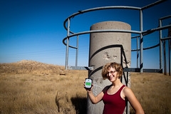
Downstairs waiting for her was yet another present. Upon opening this present, she found a red SparkFun box which many of you may be familiar with. Inside she found the NCWP. At first she thought it was a new product that we were going to carry and quickly set it aside and looked inside the box to see if there was a note or a clue. She then realized by the engraving on the front (our wedding date) that this was not a SparkFun product, but something I had made. She picked up the NCWP and turned the unit on. The LCD on the front of the NCWP came to life and displayed a welcome message. The quest had begun.
The screen informed her that her wedding ring was inside the metal lock box and her quest was to find the key before our wedding, (which was only 2 days away). I included no instructions and relied on her to follow the clues that the NCWP provided and eventually find her ring. After the welcome message was displayed, the screen cleared and the first of many clues was displayed.

The clues were cryptic in nature and all pertained to vacations we took together or events we had experienced together. The LCD displayed her progress, so she knew how close she was getting to her ring. But, let's face it, she knows me and she knew this wouldn't be easy. She quickly deciphered the first clue and was led to a photo album of ours where she found an RFID tag. After a few seconds of trying to figure out how to scan the card (the scanner was located on the bottom), the box encouragingly beeped and proceeded to display the next clue.
After several clues that continued in this fashion, I knew I would lose her interest. I couldn't make it this easy. After successfully scanning in the fourth clue, the screen cleared and displayed the message, "This is too easy for you". It then informed her that GPS had been enabled. Now the screen looked a little different and displayed "61.35 miles away" at the bottom of the clue. The next several clues would be GPS locations of some interesting locations scattered throughout southern Colorado.
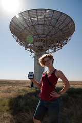
We already had a trip planned the next morning, and I'd planned all the locations all along the path of our trip. The clues brought us closer and closer to where we were getting married. After successfully progressing through the clues, we arrived at our hotel (which was itself a clue). She was rightfully a bit worried, as there were still 3 clues left before she could unlock the ring and we could get married that next morning. At this point I was feeling a bit more confident in the box, but still apprehensive because something could still go wrong! What she didn't know at the time was that the next clue was the location where we were getting married and the final two clues were not actually GPS locations.
Beforehand, I had mailed out two RFID cards, one to each of our parents. They held the final two 'steps' in the quest to find the key to unlock her ring. Upon arrival at the next checkpoint (the park in which we were getting married), the box once again beeped to indicate we were at the correct location. Then, the box cleared its screen one more time and informed her that my parents had something for her. She was continually discovering the effort involved in this whole ordeal. It had been 3 long months of planning, coding, and building to get to this point. She now realized that my parents, (who live 1,000 miles away) were in on it.
She asked my parents if they had something for her and they handed her an RFID card which she scanned. It beeped happily and progressed to the next clue which then informed her that her own parents also had something for her. We all laughed a bit because she had just called her parents the day before telling them the whole story about the box and the presents and her ring. What she didn't know was that her parents had known for weeks in advance. Everyone was in on it but her. After receiving the card from them, she scanned the final card and had completed the quest.
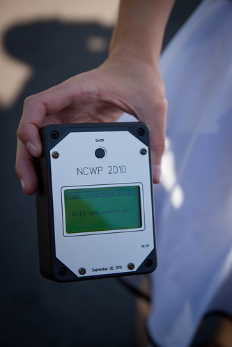
The screen congratulated her for a job well done and revealed the location of the key. The key had actually been hidden inside our car the entire time. She used the key to unlock the metal lock box and access her ring. The final screen asked the simple question "Will you marry me?"
Through her tears, I heard her say 'yes'. Shortly after, we were happily married. In all, the quest lasted 3 days and over 300 miles of travel. It was a great adventure and amazingly went exactly as planned.

The Hardware:
I had a good general idea of what I wanted to do 3 months before the wedding, but really didn't know how to go about doing it. I ended up deciding on RFID and GPS since they are relatively easy to implement and would be easy to interface with a microcontroller. I chose Arduino because I am a beginner and there are numerous resources available if you're just starting out. I cannot stress enough how expansive the Arduino community is. I didn't want to get hung up on a problem that no one had ever encountered, so Arduino was an obvious choice. I went with the Arduino Pro since it's a smaller form factor than the main board and allowed me to cram everything into the small case.

Internally, the box has two separate 'sides'. On one side (beneath the LCD screen) rests the battery and power delivery circuits. On the other end sits the Arduino, GPS, and RFID. Space was a real problem from the start of the build to the very end. I wanted everything to be as compact and portable as possible. For that reason I ended up beating my head against a wall trying to get everything as small as possible. In the end, everything barely fit.
Parts List:
Let's have a look at what all was used to create the NCWP:
- Arduino Pro 328 5V/16MHz
- Arduino ProtoShield Kit
- EM-406A GPS Module
- EM-406A Interface Cable
- ID-20 RFID Reader
- RFID Breakout Board
- Solid State Power Switch (LV)
- Buzzer
- ProtoBoard 2" Square
- 2000mAh LiPo Battery
- 5V DC to DC Step Up
- 12mm Push Button
- Serial Graphic LCD 128x64
- Battery Charger Circuit (custom made, see the 'power' section of the tutorial)
In addition to what's listed above, there were various screws, wires, cables, connectors and such. Above is the essential hardware necessary to get the unit working. Depending on the configuration of the enclosure, you may need other bits.
Enclosure:
One of my main goals was to make the finished project look as much like a commercial product as possible. The actual plastic enclosure was a cast-off we had from designing the enclosure for the GeoChron. Spaces for the LCD and button were cut out sloppily with a combination of files, a drill press, and a hot knife. It was not necessary for them to be clean cuts. The aluminum bezel would cover all this up.

Once the top plate was cut to accept the LCD and button, I needed a way to cover up the ugly plastic and make everything look more 'professional'. I've used Front Panel Express in the past for other projects, so I decided to use them again for this one. Their software is easy to use and the results can be quite nice, especially when using their lettering and inking options. I highly recommend using them for panels like this, the quality is fantastic.

Since the faceplate would be irregularly shaped, I needed to make a DXF file to import into the Front Panel Designer software. I measured the contours of the plastic top plate and got a basic outline of what the pate would look like. From here I added text, some mounting holes, and the cutouts for the LCD and on/off button. Because the LCD didn't have enough room to sit flush, It was necessary to cut out a pocket from the reverse side of the plate.


The aluminum faceplate screws to the plastic plate with 4 screws. This whole thing screws into the rest of the enclosure with 4 separate screws. And here is the finished case:

How it Works:
The box is really quite simple. I will go more into the code later, but basically it reads information from whatever is dictated by the clue (either GPS or RFID information). If what is read is 'correct' it goes on to the next clue. So, if the RFID data is equal to the stored tag, it sees it as a success and advances onto the next clue. The GPS works by determining if the location of the box is within +-0.05 miles of the preset destination. It progressed through a series of 11 steps to get to the end goal.
Power:
The most complex part (for me) of the project was how to power everything. I needed it to power an LCD screen, GPS unit, Arduino, and RFID reader. All this needed to be powered over the course of a few days (it was turned off in between some clues) and have the ability to be charged if necessary. Power is ultimately supplied from a 2000mAh LiPo battery. The battery was run through a small charger circuit I built based on the MAX1555 charger IC. With the charger, I was able to add an external 5V input to charge the battery and use an LED to indicate charging. The circuit is essentially a smaller and compact version of our LiPoly Charger. i just wanted something much smaller. The battery was affixed to the bottom of the case with double-sided tape.
The output from this was fed to a DC to DC step up converter. I needed a full 5V for the GPS and other devices and the LiPo was not enough to support this (they run about 4.2V when fully charged). The DC to DC converter takes anywhere from 1.1V to 4.5V and gives you a steady 5V output.
I also didn't want a traditional on/off switch, but rather a toggle switch to turn the unit on and off. To do this, you need a circuit to monitor a button press and provide power to the rest of the system depending on the state of this button press. The Pololu pushbutton power switch did the trick. This took the 5V output from the step up board and supplied power to the rest of the system. A 12mm push button rests on top of the Arduino with double-sided tape and is connected to the pushbutton power switch.
The DC to DC converter, charger, and power switch circuits are all housed on the protoboard. They are simply hand-wired with solid-core wire. On the same board I included the buzzer and some headers for connecting power, the battery, and the external charger input and charger LED.
The Rest:
In the other side of the case was the 'stack' that held the Arduino Pro 328 attached to a protoshield on top of the ID-20 and the EM-406A. It's generally not a great idea to have the GPS antenna so obstructed by electronics. However, this was the only way I could get everything arranged inside the case. It did work fine, but you had to be outside and the lock took a bit longer than usual.

The ID-20 needed to be facing the bottom of the case so it could most easily read RFID tags. To save space, I used the RFID breakout board instead of the RFID USB reader. The protoshield was handy for connecting everything to the 5V and GND lines.

I used stackable headers on the protoshield so I could easily attach and detach the Arduino Pro. This proved very handy for prototyping. All the signal wires were attached directly to the shield and power was connected from the power supply section directly to the 5V bus on the protoshield.
Code:
I am not a coder. I have included the code at the end of this section so you can verify this statement. However, I will say that the code works flawlessly and reliably in spite of it being messy. I'll do my best to explain how the code works, but much of it has been borrowed from the Arduino community. This project wouldn't have happened if it weren't for the TinyGPS and SoftSerial libraries. They were essential in parsing the GPS signal and allowing me to communicate with multiple UART lines. Also, the GPS quick-start guide and the Scooterputer project were immensely helpful in completing this project.
Setup:
The program starts by including all the necessary libraries, defining pins, defining communication pins, starting up the softserials, etc. In addition, it also prints out the basic information that gets the box up and running before clues are printed. This includes the progress, the basic 'graphics' and welcome message. Let's look at these lines of code:
// Include NewSoftSerial, TinyGPS, and EEPROM libraries
#include newsoftserial.h
#include tinygps.h
#include eeprom.h
//Defines communication pins for GPS, LCD, and RFID
#define GPSRX 3
#define GPSTX 2
#define LCDTX 4
#define LCDRX 5
#define RFIDRX 6
#define RFIDTX 7
#define RESETPIN 8
//Pin for speaker
int pinSpeaker = 11;
//LED pin 13 for testing
int ledPin = 13;
After including the necessary libraries and defining some pins, the program then initializes a variable that will essentially track the progress and determine which clue to read from. This variable needs to be written outside of the main program to start. I simply used a simple sketch that set a value of 0 to the specific address in the EEPROM I was using. From here, the main sketch can then read from this address and determine which part of the code it needs to use.
//address to write to the EEPROM
int address = 0;
int clue = 0;
char val = 0;
Next, baud rates are defined for the LCD, GPS, and RFID. And then we define some variables that will later be used in a distance function to determine how close we are to our target.
//Sets baud rates for LCD, GPS, and RFID
#define GPSBAUD 4800
#define LCDBAUD 115200
#define RFIDBAUD 9600//Define variables for distance calculation
#define MILES_PER_METER 0.00062137f
#define EARTH_RADIUS_METERS 6372795.0f
// Create an instance of the TinyGPS objects
TinyGPS gps;
// Initialize the NewSoftSerial library to the pins you defined above
NewSoftSerial gpscom(GPSRX, GPSTX);
NewSoftSerial lcd(LCDRX, LCDTX);
NewSoftSerial rfid(RFIDRX, RFIDTX);
From here we go into the main setup of the sketch. This simply begins all the communications and defines the pins as outputs and such.
//Gets communication ports up and running
Serial.begin(9600);
gpscom.begin(GPSBAUD);
lcd.begin(LCDBAUD);
rfid.begin(RFIDBAUD);
//Pin definitions for speaker and RFID
pinMode(RESETPIN, OUTPUT);
pinMode(pinSpeaker, OUTPUT);
pinMode(ledPin, OUTPUT);
digitalWrite(pinSpeaker, LOW);
The last thing that needs to be done is to draw some stuff on the LCD screen. First, we need to read the value from the EEPROM to determine which clue we are on, so we can display the appropriate number in the progress bar above. From there, we clear anything that might be on the LCD, draw the box that contains the progress bar, and then print the progress in that bar. After all this is done, we have the basic framework for the screen and can print a simple welcome message and then finally the clue.
//Initialize LCD Screen
clue = EEPROM.read(address);
clearLCD();
drawboxLCD();
backlightonLCD();
initProgress();
updateProgress();
welcomeMessage();
printClue();
All text for the clues are held in the "printClue()" function. It uses a switch case statement (like an 'if' statement with more than one option) which reads the clue value and displays the respective clue. Since this function is called from the setup, once the clue is displayed, it will not be cleared until the next checkpoint is reached. Also, these messages will be re-displayed if the unit is turned off and then back on again. So, once the program progresses beyond the setup section, the clue text has been displayed and the main program loop simply checks if conditions are met and if it needs to progress to the next clue.
Main:
Essentially, the bulk of the code is a simple switch statement that reads the value of the clue variable and then calls that respective function. Since the clue gets printed in the setup, nothing really needs to be done in the main loop other than monitor either the GPS or the RFID to see if they meet the conditions of moving on to the next clue.
To make things simple for me, I just made each clue its own function. They are called out from the main loop. Each clue then initializes either GPS communications or waits to read an RFID tag. If the information it gets back matches a stored value, it progressed on to the next clue. Let's look at how each one works.
RFID:
The first few clues are RFID tags that need to be read to progress to the next part of the program. Once the clue is called, it creates a string variable to store the ID of the tag. It waits to see if RFID information is available and reads the tag ID into this string. Once the string has been read, it compares the string value with the value of the ID tag I have hidden for this clue. If these strings are equal, it progresses to the next clue, and if not, it plays a failure tone.
void Clue1()
{
char IDstring[13];
int i;
digitalWrite(RESETPIN, HIGH);
if (rfid.available() > 0 )
{
if ( (val = rfid.read()) == 02 )
{
delay(10);
for ( i = 0; (val = rfid.read()) != 03 ; i++)
{
delay(10);
IDstring[i] = val;
}
IDstring[10] = 0x00; // tie off IDstring at the CR-LF
Serial.println(IDstring);
if (strcmp(IDstring, "29009410E5") == 0) // test to see if the two strings are equal
{
toneSuccess();
clue++;
EEPROM.write(address, clue);
clue = EEPROM.read(address);
updateProgress();
printClue();
}
else
{
toneFailure();
}
resetID20(); // reset after a valid read
}
}
}
After the program determines a successful match, it calls the function 'toneSuccess()' which plays a higher pitch tone (indicating success) and then increments the 'clue' variable by one and rewrites this value to the EEPROM. So now when the unit is powered on, it will start with the second clue. As was done in the setup, the progress bar is updated to reflect that a clue has been solved, and the 'printClue()' function is called to print the next clue.
GPS:
The GPS clues work in a very similar fashion, but we need to print a little bit more to the screen, as well as update the screen with new distance information. Instead of storing ID tag information, longitude and latitude coordinates are stored. These are compared against the longitude and latitude that is provided from the GPS module and a formula determines if the box is close enough to progress to the next clue.

void Clue5()
{
if(gpscom.available()) // While there is data on the RX pin...
{
int c = gpscom.read(); // load the data into a variable...
if(gps.encode(c)) // if there is a new valid sentence...
{
float latitude, longitude;
gps.f_get_position(&latitude, &longitude);
//deer trail 39.667586, -104.030630
float f_lat, f_lon;
f_lat = 39.667586;
f_lon = -104.030630;
delay(500);
float distance = DistanceBetween2Points(latitude, longitude, f_lat, f_lon, MILES_PER_METER );
Serial.print("Distance: "); Serial.println(distance);
setDistancePosition();
lcd.print(distance);
if(distance < 0.05)
{
toneSuccess();
clue++;
EEPROM.write(address, clue);
clue = EEPROM.read(address);
updateProgress();
printClue();
}
}
}
}
The distance equation was 'borrowed' from the Scooterputer project. It uses the Haversine formula which calculates the distance between two points. The distance formula returns a value which is written to a variable. If this value is less than 0.05, it progresses to the next clue. The clue progression happens in exactly the same way as with the RFID clues. It would have been wise to create a 'nextClue' function which covers all this, but I was rushed for time.
LCD:
The ugliest part of the code was the code for the LCD. It was necessary to constantly clear the screen and set the text position. I clumsily made a few functions that set the text position for various portions of the code. Also, between each clue, the main body of text needed to be cleared but the progress bar at the top needed to remain. I'm sure there are easier and more elegant ways of accomplishing this, but I was unaware of how to simplify the process.
Resources:
Here are all the files you will need for this tutorial. I removed the actual clues and locations from the code, but you could plug in any of your own clues or locations and it will work.
Conclusion:
Thanks you everyone that helped make this project possible! It was a difficult but rewarding venture. I couldn't have done it without SparkFun, but SparkFun is nothing without all of our customers and the community. We just sell 'stuff', but our customers are the ones who make it into something fantastic. Thank you to everyone who has done a project that inspired me, given me an idea, or contributed in some way to open source hardware and software. And of course thank you to my wife Kim for being the impetus for this project and also not questioning when I had to 'work late' at the office. Thanks for reading.
Very cool, and a fun/geeky wedding present!
Robert, Thanks for the cool project!
Wish List for required parts
nice, thanks!
Best ever
Thanks, she liked it ;-)
Great project, and well written. I do however have a problem. I got the project put together, and when I power up the circuit my LCD display comes up with the sparkfun splash screen, then it displays "Your Progress: 25511" inside a box on the top of the LCD with "Hello Kim!" below. Then it does nothing but keeps that display. I downloaded the program exactly, but only changed the GPS coordinates so I wouldn't get a verify error. Any ideas where to start troubleshooting?
Thanks in advance.
You will first need to rewrite the EEPROM values outside of the program. It doesn't know where you are at in the program probably.
It's reading your EEPROM value as 25511, it's expecting it to be something else.
This is a really great project, but I think I may be in over my head. After gathering all the parts the first connections I attempted was the RFID. The program defines RFIDRX as pin 6, and RFIDTX as pin 7. Is that pin 6, and pin 7 of the ID-20? I was unable to find RX or TX in the data sheet of the ID-20. It would be really helpfull if there was a pin to pin from the ID-20 to the Arduino Pro. (I can hardly wait till I get to the display) one step at a time though.
Thanks for any help anyone can give me.
Wow, you used phillips screws for the front panel? And she didn't just unscrew them? You'd have to use some foreign security bit screws or maybe super glue if the person you gave it to was a geek.
Well, there was nothing inside that she could decode. The only way to advance was to get to the GPS location, or read and RFID card. Everything is stored in EEPROM and there's no backdoor on this one. So, yeah, I just used Phillips :-)
Is there a layout, or block diagram for this NCWP? I would like to build it but I would like to work to some kind of Schematic. I'd hate to buy all the parts, and then not be able to put it together properly. It's really well written, and I guess you could do the research to figure out where all the parts go, and how they are hooked up. Just hopeing for easier because it's rated for beginner.
I was going to make a block diagram, but it turned out to be VERY time consuming. Read it more closely, write it out, and see if you have any questions. I tried to make it as straight-forward as possible.
Thanks for writing this up, never thought I'd do more than blink an LED but after reading this maybe my project ideas don't seem so unattainable. I loved the whole reason for this project, very creative.
You're welcome, and thank you for reading it. With enough research and reading, anyone can create some cool projects, it's not that hard.
Finally took the time to go back and read your whole article after seeing the short blurb when it first came out.
Wow - really am happy I took the time - and that you took the time and effort to complete this project and write about it.
I have several personal ideas I want to pursue but being a beginner to the Arduino community I've mostly been stuck in neutral just reading about other similar ideas and looking at code, filling small Sparkfun orders and compiling documentation.
This will get me off my butt. Thanks again - really appreciate the background and the details.
Thanks for the compliment! It was a ton of work to write everything up and I'm glad at least one person might benefit from it. I was a beginner with this stuff too. Having a solid project is the easiest way to learn IMO.
Well written tutorial, a solid write-up always puts the icing on the cake for any project.
thanks!
Great project and very inspiring!
I've been wanting to make a smaller lipo battery charger myself based on the 1555IC, but I'm a beginner in electronics.
Would you like to share more details on the charger circuit board? Exact dimensions? Eagle files? etc...
I'm mostly interested in charging 50-200maH batteries, would your design work for that.
Thanks
/Daniel
I'll post some eagle files later today. But it really is exactly like the lipo charger we sell with the MAX1555, just smaller. And yes, it would work for smaller batteries as well.
Original! Like it!