- Home
- Product Categories
- Level Shifters
- SparkFun Level Translator Breakout - PCA9306

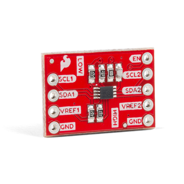
SparkFun Level Translator Breakout - PCA9306
There are a couple must-have boards that every engineer and hobbyist should have on their desk, and this PCA9306 dual, bidirectional voltage-level translator breakout is one of them! Because different parts sometimes use different voltage levels to communicate, voltage level translators can be the key to making different parts play nice.
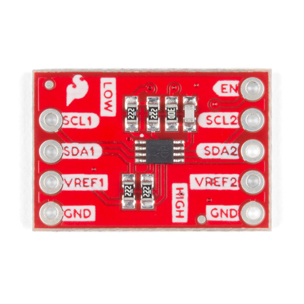
The PCA9306 is a dual bidirectional I2C-bus and SMBus voltage-level translator that's operational on the low side from 1.2V to 3.3V and on the high side from 1.8V to 5.5V. Simply apply your low and high-side reference voltages to the VREF1 and VREF2 respectively, connect your I/O and drive the Enable pin high to open bidirectional voltage translation without the use of a direction pin!
We've updated this classic board to use a new footprint as well as adding a second ground pin and breaking out the enable pin.
- Schematic
- Eagle Files
- Hookup Guide
- Datasheet (PCA9306DC)
- GitHub Hardware Repo
SparkFun Level Translator Breakout - PCA9306 Product Help and Resources
Core Skill: Soldering
This skill defines how difficult the soldering is on a particular product. It might be a couple simple solder joints, or require special reflow tools.
Skill Level: Noob - Some basic soldering is required, but it is limited to a just a few pins, basic through-hole soldering, and couple (if any) polarized components. A basic soldering iron is all you should need.
See all skill levels
Core Skill: Programming
If a board needs code or communicates somehow, you're going to need to know how to program or interface with it. The programming skill is all about communication and code.
Skill Level: Competent - The toolchain for programming is a bit more complex and will examples may not be explicitly provided for you. You will be required to have a fundamental knowledge of programming and be required to provide your own code. You may need to modify existing libraries or code to work with your specific hardware. Sensor and hardware interfaces will be SPI or I2C.
See all skill levels
Core Skill: Electrical Prototyping
If it requires power, you need to know how much, what all the pins do, and how to hook it up. You may need to reference datasheets, schematics, and know the ins and outs of electronics.
Skill Level: Rookie - You may be required to know a bit more about the component, such as orientation, or how to hook it up, in addition to power requirements. You will need to understand polarized components.
See all skill levels
Comments
Looking for answers to technical questions?
We welcome your comments and suggestions below. However, if you are looking for solutions to technical questions please see our Technical Assistance page.
Customer Reviews
4 out of 5
Based on 3 ratings:
Does the Job
Used it for an LCD at 5 V to interface with 3.3 V I2C.
pca9306
Performs as expected. However, if headers are installed, the spacing between the low and high side headers is not a multplle of .1". So, the board won't plug into a standard breadboard.
Good level translater but pcb needs re-designing
This board works perfectly however there is a problem with the physical circuit board. Although the pin spacings verticaly on either side are the correct 0.1" spacing for stripboard\breadboard etc, the left to right horizontal spacing does not line up with the 0.1" holes\sockets and is therefore quite difficult to mount on these types of prototyping boards forcing you to solder the pin headers at an angle, which makes insertion and removal difficult. If the pcb could be re-designed with the correct horizontal (multiple of 0.1") spacing then this would really improve the mounting of the board.
Thanks for the feedback!
The breakout has two pin headers... pitch is 0.1". Ok. But the distance between both connectors is not an exact multiple of 0.1 "... this makes it a bit of a hassle to plug the module into a prototype board. Why is the connector spacing not an exact multiple of 0.1"?
A fair question...
You can submit a "Feature Request" under the Issues tab of the GitHub repository, so that there is a record of it to be considered in the next revision.
Please include headers with the product! Currently, this board does NOT include headers.
Just bought a bunch of them from Digikey. They still have the horrible non-0.1" grid distance between the A row of pins and the B row of pins. Ugh!
I don't have a GitHub account and I'm not signing up just to complain. Sorry guys, this PCB layout is a dud. Please fix it.