- Home
- Product Categories
- Audio
- SparkFun SparkPunk Sequencer Kit

SparkFun SparkPunk Sequencer Kit
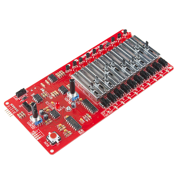
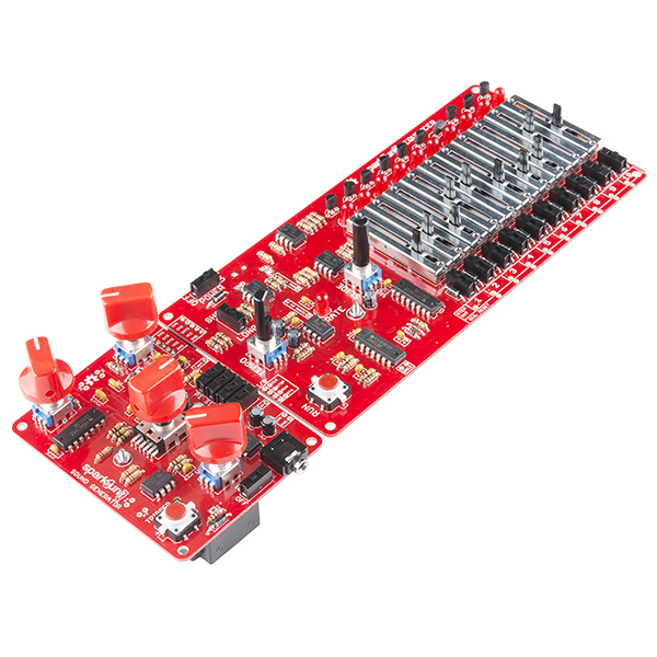
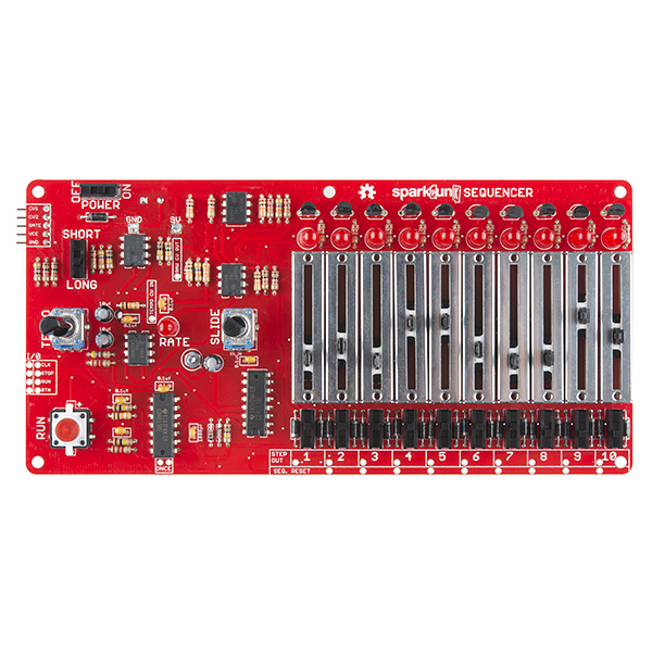
The SparkFun SparkPunk Sequencer is a musical control voltage sequencer designed to control the SparkPunk Sound Kit. With the pair, you can create ten-step musical motifs, but there are hidden opportunities in the sequencer: it can be modified and connected to external hardware in clever and interesting ways. The SparkPunk Sequencer cycles among ten steps, reading the slider and switch for each, producing corresponding analog voltages on the output pins. It offers hands-on control, with its array of knobs, sliders, and switches while seamlessly integrating with the SparkPunk Sound Generator for your creative musical enjoyment.
Unlike typical sequencers, this kit offers many tricks and modifications like adjusting Sequence length by connecting solder pads together at the bottom right of the PCB, routing pins to make a one-shot sequence playback, even creating a tempo clock or influencing the analog signals of LEDs. If any of that sounds too simple you can interface with more hardware like synchronizing multiple sequencers and more!
Be aware, the SparkPunk Sequencer comes as a solderable kit that is slightly more complex than most SparkFun soldering kits with a greater variety of components.
Note: The SparkPunk Sound Kit is not included with this kit and will need to be purchased separately.
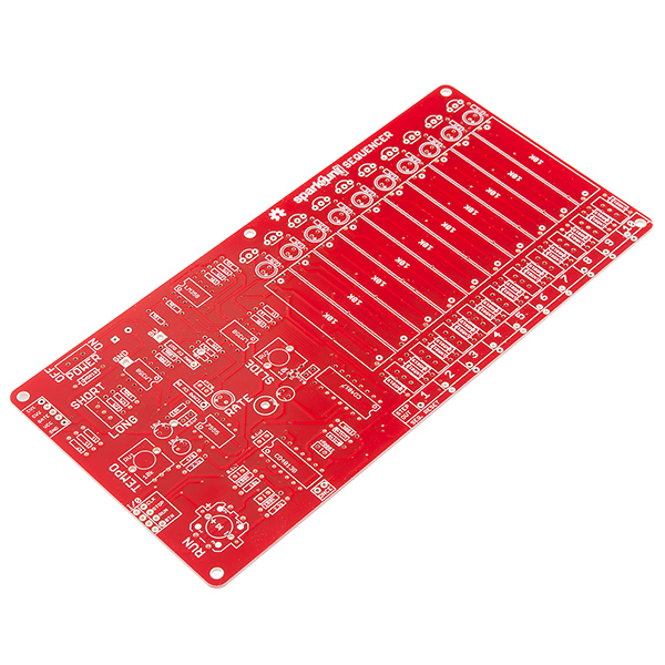
- 1x SparkPunk Sequencer PCB
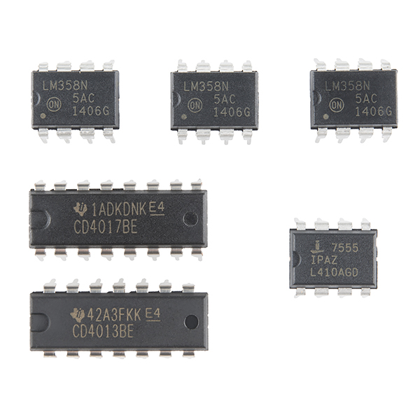
- 1x CD4017BE IC
- 1x CD4013BE IC
- 1x ICM7555 IC
- 3x LM358N IC
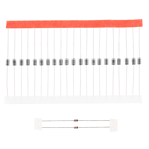
- 2x 1N4148 Diode
- 21x 1N5819 Diode
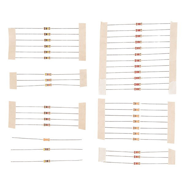
- 1x 33K Ohm Resistor
- 1x 470 Ohm Resistor
- 1x 47 Ohm Resistor
- 3x 47K Ohm Resistor
- 3x 22K Ohm Resistor
- 4x 1K Ohm Resistor
- 6x 100K Ohm Resistor
- 7x 10K Ohm Resistor
- 12x 2.2K Ohm Resistor
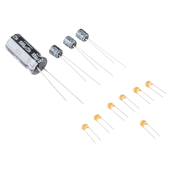
- 1x 1000uF 25V Electrolytic Capacitor
- 1x 1nF Ceramic Capacitor
- 3x 10uF 25V Electrolytic Capacitor
- 6x 0.1uF Ceramic Capacitor
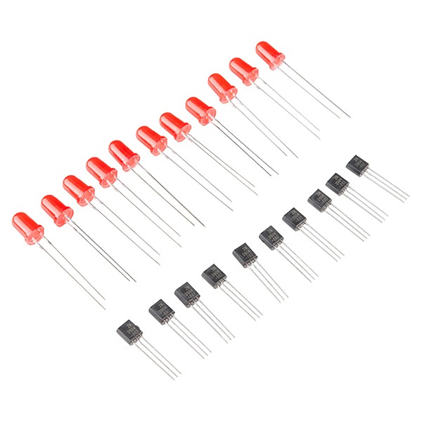
- 10x 2n3904 NPN Transistor
- 11x Red LED
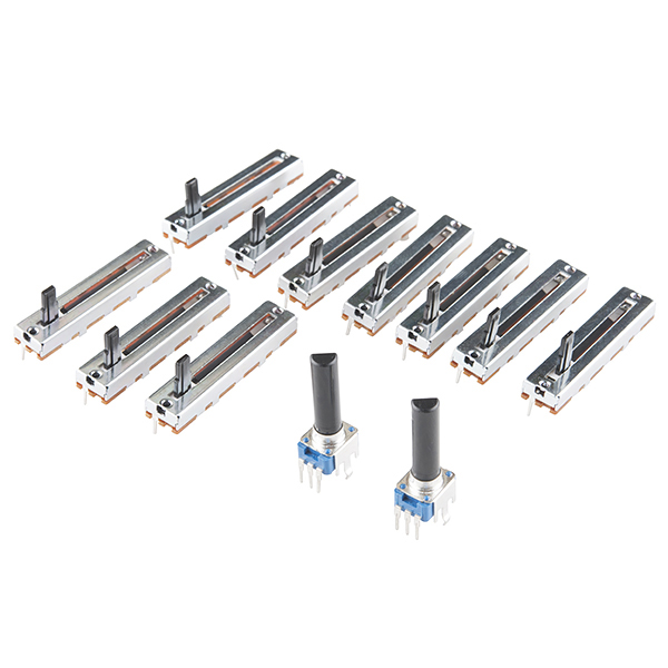
- 2x 10K Ohm Rotary Potentiometer
- 10x 10K Ohm Linear Slide Potentiometer
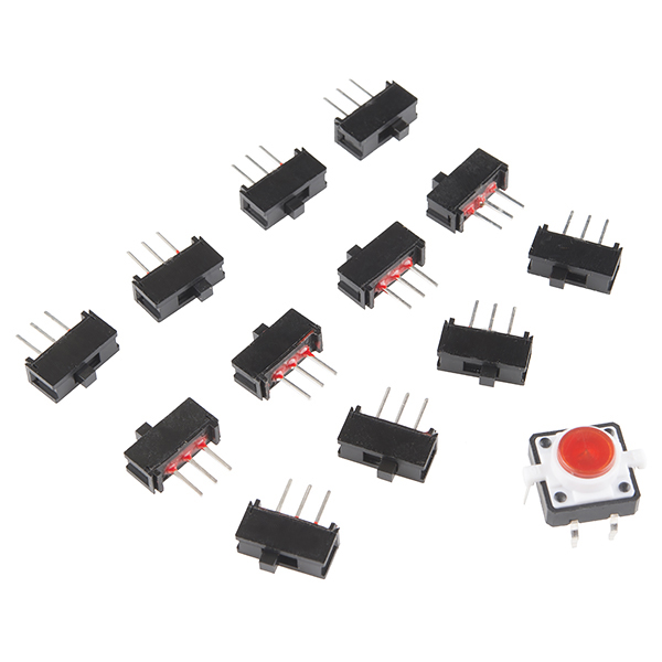
- 1x Red LED Tactile Button
- 12x Mini SPDT Switch
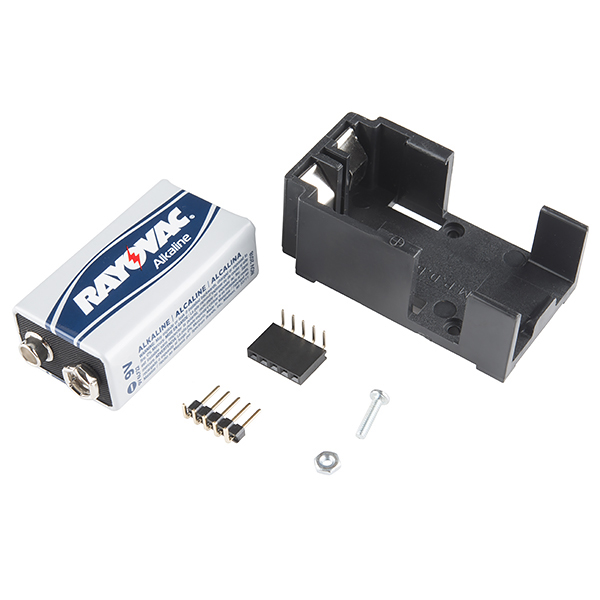
- 1x 5-pin right angle male header
- 1x 5-pin right angle female header
- 1x 9V Alkaline Battery
- 1x 9V Battery Holder
- 1x 3/8" 2-56 Phillips Machine Screw
- 1x 2-56 Nut
- CD4017 based 10 step sequencer
- 1-10 step sequencing with easy modification
- Long/Short, Tempo, and Slide Control
- Hooks directly into the SparkPunk Sound Kit
- Only one 9V Battery needed to power the SparkPunk Sequencer and SparkPunk Sound Genrator
- Schematic
- Eagle Files
- Hookup Guide
- Theory and Applications Guide
- Datasheets:
- GitHub (Design Files & Sims)
- Product Video
SparkFun SparkPunk Sequencer Kit Product Help and Resources
SparkPunk Sequencer Hookup Guide
August 14, 2014
How to assemble and use the SparkPunk Sequencer kit.
SparkPunk Sequencer Theory and Applications Guide
August 14, 2014
Examine the inner workings of the SparkPunk Sequencer, then explore some modifications and alternate applications.
Erratic/No Response from "RUN" Button
Sometimes the issue is with a broken contact from the "RUN" button's LED. If this is the case, the red bulb for the button won't light up when you try to run the board.
Otherwise, I found two solutions that seem to work around the problem:
The gate output at the top left of the board by the on/off switch is floating. (I haven't had a chance to confirm if it the source of the issue.) By grounding the GATE pin or using a pull down resistor (low resistance), the board does seem to work more consistently.
I also found that you can momentarily short the STOP and BUTTON breakout pins (left of the "RUN" button) to kind of trick the board to start sequencing. Just press the "RUN" to stop it again.
Core Skill: Soldering
This skill defines how difficult the soldering is on a particular product. It might be a couple simple solder joints, or require special reflow tools.
Skill Level: Rookie - The number of pins increases, and you will have to determine polarity of components and some of the components might be a bit trickier or close together. You might need solder wick or flux.
See all skill levels
Core Skill: DIY
Whether it's for assembling a kit, hacking an enclosure, or creating your own parts; the DIY skill is all about knowing how to use tools and the techniques associated with them.
Skill Level: Noob - Basic assembly is required. You may need to provide your own basic tools like a screwdriver, hammer or scissors. Power tools or custom parts are not required. Instructions will be included and easy to follow. Sewing may be required, but only with included patterns.
See all skill levels
Core Skill: Electrical Prototyping
If it requires power, you need to know how much, what all the pins do, and how to hook it up. You may need to reference datasheets, schematics, and know the ins and outs of electronics.
Skill Level: Rookie - You may be required to know a bit more about the component, such as orientation, or how to hook it up, in addition to power requirements. You will need to understand polarized components.
See all skill levels
Comments
Looking for answers to technical questions?
We welcome your comments and suggestions below. However, if you are looking for solutions to technical questions please see our Technical Assistance page.
Customer Reviews
5 out of 5
Based on 3 ratings:
1 of 1 found this helpful:
Good synth fun
This in combination with the Sound Generator is a fun intro to DIY synths. The instructions are excellent and this is an easy project to build. It even impressed the teens in my house and that is no small feat.
1 of 1 found this helpful:
What a great little unit!
I mainly purchased this kit because I love to assemble kits, and I wasn't expecting how much fun I would have playing this instrument. I purchased it along with the SparkPunk sound kit, and the sounds you can make are limitless or so it seems. I have it plugged into a small 50 watt guitar amp, and every time I turn it on thinking I'm going to kill a couple of minutes it turns into an hour, it's that addictive. It's well made and designed, and once you add some knobs, two for this unit and 3 for the sound generator, you're in for some very funky- yet hypnotic tones.
Used in performance!!!
So the build of the Sequencer rapidly and easily followed my build of SparkFun SparkPunk Sound Kit - KIT-11177. I plugged them both together with immediate good result. Then I added the combo as part on my performance package providing audio to a transducer enhanced audio object at David Tudor's RAINFOREST IV concert at Brown University. Thank you.
Can you sequence other things with this? Light boards, Mp3 triggers and such?
It can, depending on how clever your are at interfacing it. Nick discusses one way to do it in the demo video, driving the tap tempo input on a pedal from the sequencer clock.
There's also some discussion of adding more hardware in the applications guide.
More sophisticated applications will probably involve a microcontroller, and there are more direct ways to have a microcontroller read a bunch of sliders. This rabbit hole goes as deep as you care to explore.
10 steps? Errrrr... does it permit setting the sequence length shorter than 10, for those of us who aren't that proggy and would rather play in common time? (Meaning, 8 steps would be far more sensible.)
You totally can, check out the Theory and Applications Guide in the Documents section for instructions on adjusting the sequence length.
The hookup guide and the theory and applications links dont work. Just take to main learning page.
Well... that's lame. They should be up now! :)
Here's my blog post on my build
Thanks for the link!
I'll go talk to the folks who put the parts in the kits, and see if we can switch things so the really tiny components aren't in the same baggie as the sliders.
For anyone who didn't click through tho read it, there's also a nice demo video of the SparkPunk paired with the Sequencer in there.
Folks, I just finished building mine, and hope to have a blog post soon... but take their word for it, this is not a 1 hr project. I came in at about 3 hrs, and probably should have taken a break after hour 2.
The majority of this unit goes together like a dream. Didn't even touch my vise or third hand. I was rocking until I hit the 5 pin connector that is made to marry up with the SparkPunk Sound Kit (which I have). Unfortunately this is a mess now because a) I didn't use the approach they recommend on the sound kit side since it was built a few weeks back, and b) the sequencer board is very unwieldy once you get all the parts on. Very difficult to put into a vise. So what I have now is a bit of a Frankenstein connection just to get through a performance I am going to do with this (in three days!!).
I'd recommend a break after you put the sliders in, then come back at it with a fresh set of eyes.
Should use the trick i do for connectors. Fill in one of the holes with solder. Then heat that up and shove the part in and remove soldering iron while positioning the part. Then finish up soldering the rest of connector
Heres a time-lapse video of it being put together.
http://youtu.be/s-o9PDeK_OM
any chance to know more about synchronizing the pedal from clock of the sequencer? how does this mosfet work ? i d'like to set it up ... any link would be helpfull... thanks
Hello, I also got the nut lodged in the slider accident, apart from that it all went well. I'm now tryng to get it to sync with the beat step, but as of now with no success. i injected clock at clock inpunt of the punk and stat/stop at the btn input. Any pointers would be greatly apreciated
First off, I take it you've seen the section that describes synch in the theory and applications guide? I take it you cut the traces on the synch port, and are injecting the new signals on the pads marked "I" that are nearer the edge of the PCB?
Also, you might want to re-check the description of the run/stop and button signals. Run and stop should be logic signals that are the opposite of each other - "run" should be high when the sequence is running, while "stop" should be low. Then when stopped, they should trade - "Stop" should be asserted, and "run" should be low. You can use a voltmeter to verify that those signals are behaving correctly.
I've looked through Arturia's documentation, and I'm not finding any description of getting a clock out of the unit. They mention CV and gate, but not clock. Do you have any links that describe external clocks you could share?
Hello, thanks for your answer.
I used the midi out of the beat step, tapped clock from pin 3 (top of my head here, might be other) and start/stop, which I injected to button since on a midi din plug it's from the same pin. I must confess not rtfm ☺, so no, didn't cut the traces. Will read further into it and come back, thanks again
I think there's a step missing in there.
MIDI is a serial protocol, using digital messages to describe a musical performance. There's a single line on there that carries all of the messages, which include note-on and off, clock synch, and other things like the sustain pedal and pitch bender. It's a bit confusing, but 2 or 3 of the 5 pins in the MIDI connector are unused.
Even more confusing, Roland used the same connector when they implemented DIN-sync, one of the precursors to MIDI.
To turn MIDI into a clock suitable for the Sequencer, you'd need to use a microcontroller. It would watch for the synch related messages (start/stop/continue and clock pulses), and turn them into inputs for the sequencer. A Red Board with the MIDI Shield or MIDI breakout would get you most of the way there.
so I am thinking about hacking this for robotic control purposes, could it realistically be hooked to an x-bee and control something else? or does it only connect and interface with the SparkPunk?
It's not stuck strictly to the SparkPunk, but (as they say in electronics textbooks) other applications are left as an exercise for the reader.
The theory and applications guide covers some of the circuit details, such as what the internal signals look like, and where you can tap them off for other circuitry.
If you're looking for a way to just hook 10 sliders up to an Xbee, there are probably easier methods. You can use an analog multiplexer to hook lots of sources to a single ADC channel, for instance.
My kit was missing the 470 Ohm 1/4 watt resistor and the nut for the battery pack. I have resistors on hand, so no huge deal I guess. And it would be silly to ship me one silly nut.
You should also doublecheck the insides of the sliders.
On one of my pre-production kits, I thought the nut was missing. It had actually fallen through the slot on one of the sliders. Pointy tweezers extracted it.
As a matter of fact, that is what happened. It took me a while to get it out, even with the right tools. I'd recommend that they package this differently to avoid this. Still not sure where the missing resistor is. But I'll let them know.
Hah, almost the same exact thing here - I was short a 2.2kOhm resistor and the nut was also hiding in one of the sliders.
Email techsupport@sparkfun.com. They can probably work something out (like store credit for the nut so you can get a replacement with your next order). Either way its good to know, helps us keep track whether this is a problem or just a one time thing.
I love Nick's demo videos, but this one unfortunately leaves me confused... I'd really like to see another take without the lights and other music gear and only with the SP gear. I'm still not sure what this sequencer does with my SparkPunk?
Can it be MIDIfied somehow? This way people could control their modern synths.
Also, I don't mind the 10 steps (instead of the usual 8). Will force me to think outside the box and create different musical pieces. The World has too many barriers and constraints! Let's free our minds! But it's nice that I can get it to do 8 or 4.
Yes, you can add MIDI, using something like a RedBoard with MIDI shield.
The easiest thing would be to add a MIDI input, and extract the timing clock and run/stop commands. Then it can chase external sequencers. Just inject the signals into the sync I/O port.
Going the other way, with a MIDI output, is a bit harder. If you wanted to try it, I'd set the micro up to interrupt on a pin, which would be tied to the clock output. When you see a rising edge on the clock, chek the gate. If the gate is high, take an ADC sample of the control voltage output, then convert that into a MIDI note number, and send a note on. On each new clock, send a note off, if you had previously started a note.
Slide on the CV will mess that scheme up - MIDI doesn't have a good way to represent the note changing like that. There are pitch bend commands in MIDI, but they don't have a guaranteed range.
If you really wanted to build a MIDI step sequencer, it's probably easier to take inspiration from this one, but design the hardware from scratch, with a microcontroller at it's heart.
Umm, yeah. A ten step sequencer is somewhat useless for music. 8 or 16 steps is preferable for those working in 4/4 time.
You can change it to 8 steps if needed. Check the Theory and Applications Guide for instructions on adjusting the sequence length.
So many sliders... must control them all! WANT! Do you have any plans to carry a narrower knob for the slide pots? COM-09120 is too wide to fit when the pots are this close together.
Is the SparkPunk Sound Generator hte SparkPunk Sound Kit?
correct, updated description to make more sense.