- Home
- Product Categories
- Data Loggers
- SparkFun Logomatic v2 - Serial SD Datalogger (FAT32)

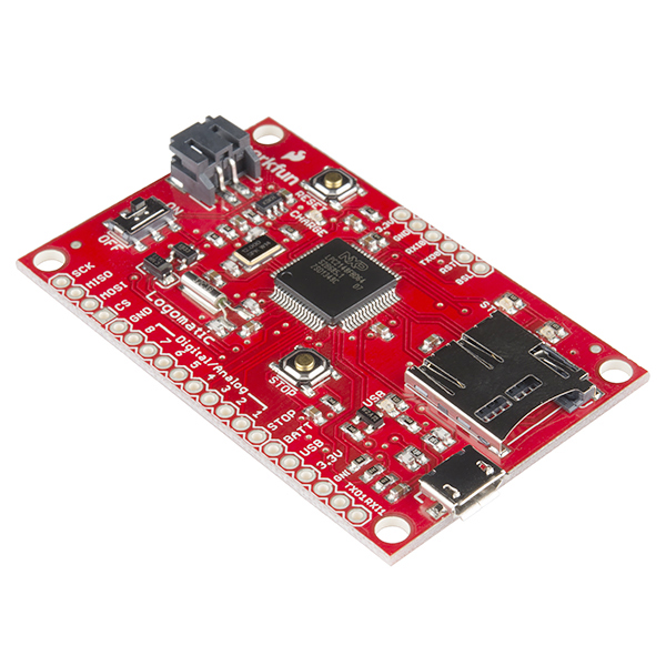
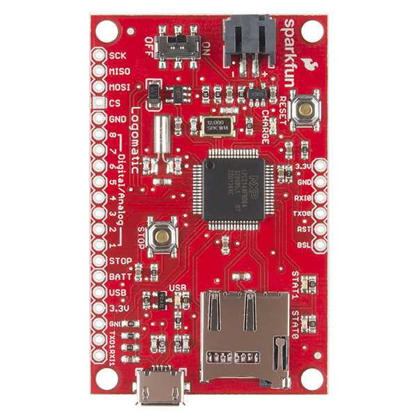
SparkFun Logomatic v2 - Serial SD Datalogger (FAT32)
The SparkFun Logomatic v2 takes everything we learned with logging analog or serial data from your projects over the years and boils it down to an easy to use device, that is now more adaptable than ever! Version 2 incorporates the LPC2148 with microUSB, battery charging, FAT32 formatting, and microSD support. This allows us to use the SparkFun LPC2148 USB bootloader for even easier and faster modification of the firmware. No programmer required!
The Logomatic v2 uses a USB mass storage stack to appear under any operating system as a flash drive. Logs are created in FAT32 format on the microSD media and can be downloaded quickly over a USB connection by dragging and dropping the text files from the device. The microSD card can also be removed and inserted into a card reader to download the logs.
This board comes with a JST connector to be powered from our line-up of LiPo batteries or other power sources up to 7.5VDC. If you choose to use LiPo batteries, the Logomatic v2 has a built-in charger to charge batteries off USB.
The Logomatic v2 ships with basic serial text and analog logging. Users can easily start with this firmware but are encouraged to modify the firmware for their specific requirements. It's a truly flexible logger.
- LPC2148 ARM7
- 512K user flash
- 10 available GPIO pins
- 2 Status LEDs
- microUSB Link LED
- External interrupt
- microSD socket
- Compatible with most SDHC flash media (no longer limited to 2GB)
- Built-in MCP73831 USB charger (500mA max)
- Built-in USB mass storage device bootloader
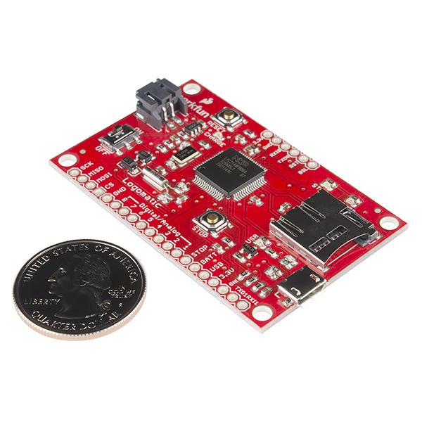
- 1.5x2.4"
- Schematic
- Eagle Files
- Hookup Guide
- Datasheet (LPC2148)
- Alternative Event Logging Firmware
- GitHub (Design Files & Firmware)
- Product Video
SparkFun Logomatic v2 - Serial SD Datalogger (FAT32) Product Help and Resources
Logomatic Hookup Guide
May 29, 2014
Basic introduction and hook-up guide for the SparkFun Logomatic.
ADC Input Values
ADC inputs are logged as a 10-bit value just like in Arduino. (0-1023)
Comments
Looking for answers to technical questions?
We welcome your comments and suggestions below. However, if you are looking for solutions to technical questions please see our Technical Assistance page.
Customer Reviews
3.5 out of 5
Based on 10 ratings:
1 of 1 found this helpful:
Great little Logger/Controller
With 8 IO lines, you have a wide variety of options to control/read. With a simple mod, you can control when the attached battery charges when not plugged into the micro USB. I am so glad that this is now a FAT32 version therefore it can use larger SD cards and I can now easily buy some for in it. It is a very stable board, the programming can throw some people off. I would recommend this Logger to anyone who doesn't have the time or resources to make their own.
1 of 1 found this helpful:
Logs great, but clarity regarding the serial logging is needed
The bad: From the description of the product, it hints that the unit can accept serial logging, however, this is only true if you are using TTL level logging. Peripheral MAX232 for RS232 is still needed to talk to PC or other devices that are sending out RS232 data. In this sense, it is not a plug-and-play device. Minimal hardware design is still needed. Improvements needed (IMO)
Add a MAX232 to talk to PC. Improve description to specifically mention that this is only a TTL serial logging device, and additional parts are needed to talk via RS232.
The good: 1) Documentation is spot on! 2) I found new tools to use and debug with. 3) logging and code manipulation is easy. 4) Portability is fantastic. 5) Large data storage card is fantastic and very desirable.
3 of 3 found this helpful:
Works for Slow Sampling, Short Duration Applications
This thing works if you want to log at slow-ish speeds for short periods of time. The sample range is from 2kHz max (for 1 channel I believe) down to 1Hz (which is still too fast in some applications). So this is more of a long-haul type of logger, which makes sense.
But "long" is a loose term here. I've used the thing for some time now and I can't seem to get the logger to last longer than 1.5 days on a 2000mAh LiPo battery logging at the slowest speed. Considering the size of the battery and the sampling frequency, this is pretty abysmal. One of the culprit is a red LED that stays on all the time, but I also suspect the MCU doesn't go to sleep, even when sampling at 1Hz.
I suppose one could depopulate the LED go change the firmware to resolve some of these issues, but I was really hoping to have this work out of the box.
If you're looking to log at a slow-ish speed for a short period of time (e.g. capturing data from a launching rocket), this might be the logger for you. Otherwise, Sparkfun's OpenLog board (https://www.sparkfun.com/products/9530) might be a better fit.
P.S. As an aside, the config file is needlessly confusing and I always end up having to refer back to the hookup guide to help me out.
1 of 1 found this helpful:
not well documented and buggy code
I got this logger to use for a project I am working on. I started with using it to log analog values and modified the code from there. The information below is related the stock code that comes with the logger.
Pros:
- Records to SD card
- Can be run standalone
Cons:
- buggy firmware (see below)
- The schematics are poorly written. Several of the labels on the microcontroller pins do not match up with the labels on the connector pins.
- The code does not have many comments so it takes a while to figure out what is going on before trying to modify the code.
- The connector labels on the board do not correspond to sequence the analog channels are read in the code
The analog ports are read and recorded in the following sequence:
AD1.3
AD0.3
AD0.2
AD0.1
AD1.2
AD0.4
AD1.7
AD1.6
The board has the following connections
Analog 1 connects to AD0.3
Analog 2 connects to AD0.2
Analog 3 connects to AD0.1
Analog 4 connects to AD0.4
Analog 5 connects to AD1.7
Analog 6 connects to AD1.6
Analog 7 connects to AD1.2
Analog 8 connects to AD1.3
Software bugs and Fixes
.1. The code does not read the frequency from the config file on the SD card right. It will not read a frequency of less than 10 hz from the SD card and does not run at 1 to 9 hz. I changed the program to use a hard coded frequency to run at 1 hz. I changed this line:
“T0MR0 = 58982400 / freq;”
to this
“ freq=1;
T0MR0 = 58982400 / freq;”
.2. The code does not configure the baud rate right at 115200 baud. I suspect some of the other baud rates are also not configured right but I have not checked them. The setting for modes zero and 1 on the logger are:
“U0DLM = 0x00;
U0DLL = 0x20;“
The settings above work out to 117187 baud.
I found this because I was having problems with getting garbage serial data when reading a long string. I changed the baud settings to the ones below and the serial data was read in correctly.
These settings work out to 115215 baud and work better:
“U0DLM = 0x00;
U0DLL = 0x0C;
U0FDR = 0x7C;”
If you see page 151 in section 10.3.5 of the LPC214X manual it has working settings for most of the common baud rates. I found a copy of the manual here: http://www.nxp.com/documents/user_manual/UM10139.pdf
Note that the table in the manual is for a 20mhz clock, and the logger is running at 60mhz so a 3x scale factor is needed
.3. If you are using the second SPI port (the one brought out to connectors, port 0 is used for the SD card) you need to change the program to use the "LPC214x.h" header and register map instead of the "LPC21xx.h" header and register map. In the 2148 processor the “spi” port that is brought out is actually a SSP port and the register map is different. The SSP port can be configured for “Motorola SPI, 4-wire TI SSI, and National Semiconductor Microwire buses”(from the datasheet I linked to above)
note: edited multiple times at first posting to get formatting right
Hello!
Sorry about the issues with it. We really appreciate the constructive feedback, and will keep it in mind for future revisions of the product.
Good device for the money
For the price, this is a decent device. It does have some weak points though. The microusb connection to the board is flimsy. Don't expect to be able to connect/disconnect more than a few times before it starts to come away. I have connected a short microusb extension cable so that the stress of repeat connects is transferred away from the board. Before that I lost a few boards when it broke away. There should be a breakout for the on-off switch so that it can be operated external to whatever housing you put the board in. Essentially you have to toggle the switch each time you connect to USB, so this needs to be made easier.
Works well
The voltage in pin is labeled "Batt". It is versatile, having both ADC pins and SPI, but both can not be used at the same time. The addition of SPI C++ code examples for the various Arduinos would be very helpful.
Great little monitor/logger
Cheap, open source code, nice layout with pads to allow a mezzanine signal conditioning board. love it
Testing one more time
Gave the device a bad review but understand that it may have been the voltage from a 2S LiPo. Don't use a 2S LiPo on this board. Will review once again soon. Customer service has been excellent in assisting us with our troubles even though we may have caused the issue.
This is an exceptionally large failure rate. Please contact techsupport@sparkfun so they can help you troubleshoot what happened with your boards. If there was indeed a failure on the board hardware, we can get you set up with replacements.
Not easily compatible
The data logger was recommended to me by a Sparkfun tech. with the understanding that it would easily connect to a 9DOF sensor stick, however, it does not. The problem is that the sensor transmits with I2C but the logger does not and we could not easily find any open sourced programming to support the two components. We finally ended up buying an Adafruit 9 do that has better supporting programming And we now hove no use for the components we purchased from Sparkfun. I'm sure they work fine but the combination for our use did not work.
Scott N
Hi, This logger is setup to log analog or serial data from your project. If you want to log information from an I2C device you would need something like an Arduino to interpret the I2C line, and transfer the data out over serial. Sorry these parts didn't fit your needs.
Good but frustrated ...
... because I need to time stamp my analog data but the few existing SW examples are too complicated or not enough documented for me to adapt the firmware by myself !
I'm reading comments, and technical info, and it looks like this V2 Logger max's out at 2KHz sampling?
Am I reading that correctly. I have a motor which will be spinning at 3500 RPM and has an encoder on it that outputs 20 pulses per revolution. Yeah, that's 70K pulses per minute (~1700 pulses per second).
Am I understanding that this logger will be able to keep up?
Moreover, can it keep up at this rate with multiple sensors running at this kind of speed? Because, I our team has a robot with 6+ motors, some of which we'd like to track tightly for variances in speed.
Thanks for the assist?
Hi, I'm having some issues logging data from UART on this board. basically, I only get it to log data when I push the stop button. Is anyone else having this problem? I tried emailing tech support but no response.
I'm powering the board from the arduino 5V rail into the BATT pin with my arduino TX and RX pins connected to RXI0 and TXO0 and simply periodically sending short UART serial sentences to log. This behavior is on multiple boards, so that makes me think I'm not just dealing with a busted board and that I'm just missing something.
Figured out what was happening. Basically, it seemed like nothing was being logged because nothing was being logged because my test program was logging short sentences like 1 transmission per sec. But in mode 0 where the logomatic logs everything from UART0, it's filling up the whole 512 byte buffer before logging, which was just taking a long time to get to. So that's an entire 512 characters that it needs to collect before logging unless the stop button is pressed. (Also don't you just love it when you figure something out in experimentation and then find the 5 lines of documentation explaining the problem immediately after?)
Hi,
What is the max write rate of this module?
Hi all,
I am making an embedded system with this and aim to put in in a 3D printed case. I'd like to have a panel mount ON/OFF switch. I figured the Logomatic has a SPDT switch, and as such bought some panel mount ones. Does anyone know what type of switch this has? And the best way to go about soldering on a panel mount one?
This is my first embedded system, and I'm a relative noob in general. Thanks in advance for any guidance!
This is the switch that is onboard the Logomatic. You will want to solder jumper wires from your panel mount switch to the appropriate pins on the Logomatic (double check the Eagle files if you aren't sure which ones you need to connect). Alternatively, you could leave the switch on the Logomatic on the "ON" position, and add the panel mount switch in-line with your power supply to the Logomatic.
Thanks! I actually thought of the in-line idea, but I thought it would prevent the battery from being able to be charged via USB if the switch couldn't go to the "OFF" position...
How did you find out what model of switch the Logomatic has?
Finally, I am also interested in adding a RGB LED to indicate the battery voltage. The setup for that and code is easy. My only problem is that when I do an analogRead of the voltage on the "BATT" pin, the numbers are way off. I know the code is correct for converting to the correct voltage. I used my multimeter to read the voltage between the "BATT" pin and ground...it will intermittently display the correct voltage (4.2V, for example) but not steadily. Did I just do a poor soldering job, or cause damage from too much heat?
Thanks again for your help.
Hi,
Just wondering, is it possible to use both the UART and ADC channel(s) (between 1 to 3 channels) to log simultaneously with this logger? Thanks
I messed up the firmware and now my device is bricked.May someone sent me the original firmware? I'll try to upload to the device with via ISP...
thank you Luca
The firmware is in the GitHub repo linked above. This however is an ARM processor, so you'll need the correct programmer to update it. Please check out this tutorial on the bootloader,
Why, oh why (!) didn't you include the ability to have a small coin cell to back up the RTC???? I've been asking for this for years!!! Yes, the entire device can run of a LiIon battery... but all it takes is a header to add an optional coin cell (or even the pads for a header!) to make it so that the RTC is useful!
So sorry about that! We try to include all the feedback we can in new revisions, but apparently this one fell through the cracks. I'll get it added into a new bug right now for the future rev.
Note that you can sleep the processor but keep the RTC running on the main power supply. The LPC RTC has a great alarm feature to wake it back up at a specific time and date as well.
Can I use this to route power from a Li-Po Battery through the logomatic to an Arduino?
these aren't the lagers you're looking for
I am using the Analog channel, and want to record at 10kHz. Has anyone succeed doing it? I am pretty sure that there are a lot of lost samples...
Does anyone know how to/if it's possible to use this to periodically wake/turn on a Yun. I would like to send the datalog over wifi once a day. Any ideas/thoughts would be great! Very new here, apologies if it's a dumb question!
Hi,
What is the maximum current that we draw out of the 3.3V output? The LDO ref is not provided.
Greg
FYI, you can also check my Open Source Voltage logger and Pressure & Temperature Logger projects that run on on my Scorpion Board. It uses log_fs a simple, but robust record-based file system for AT45D DataFlash that I'm quite proud of.
Could you use this to emulate an SDIO card, or an SDHC card? I want to test something and be able to emulate the card plugged into a card slot. Thanks!
This isn't really designed to interface with another card slot, since there is one on-board. However, you could hook it up via the data lines to another board's SD lines, but you'd still have to put an SD card in the Logomatic to have it function properly.
Has anyone modified the standard code to respond via UART when an input is triggered? ie, log all incoming serial data AND if any Digital Input goes high send "Digital x Pressed" out the UART? "Digital x Pressed" would also be logged to the SD Card.
Does it Log Binary+ ASCII (in short anything) mixed data thrown at it at 115200 baud in UART '0' mode? I know the OPENLOG does, just wanted to know if this device does the same.
Can anyone point me to an example of how to use the RTC on this device?
Yes, having the RTC battery input would be very useful, not to mention that the voltage regulator draws more power that the CPU in power down mode. Also, the voltage divider network to read the battery voltage uses 1Meg resistors, but the input impedance of the ADC is approximately 40K - huge measurement error!
Is there a sample output file posted anywhere?
@Spakfun: The Github link above (30/June/2014) shows the firmware was last updated 10 months ago. It also shows the old 10216 product photo and information. Can this be updated to reveal the most recent firmware, and can you please confirm that this new firmware is suitable with the V2 hardware (prod code10216) Fanks!
Ah, yea we have to get the links updated between the two versions. The new firmware is compatible with the old v2 hardware!
I was wondering if the Jumentum software (http://jumentum.sourceforge.net/) could be loaded onto this, then you could write your own BASIC program to do the data acquisition.
I have the Logomatic v2 that I ordered in 2013. The PN is WIG-10216 and it is from Batch # 30804. Can this version have its firmware updated to run the new FAT32 firmware or did you make a PCB change since then? If I'm remembering correctly, I think the one I bought only had FAT16 on it.
Yup, you should be able to update the firmware without issue. We did make some minor hardware changes, but mostly to help improve our production process and minimize errors during the builds.
When I first saw this I was like what is a logo-matic (shows company logo?). Then I realized log-o-matic. I feel dumb.
I'm intrigued.... Why is the shipment of this product to some territories restricted?
It's a general restriction on the LPC ICs.
So... why is this restricted but the MBED board not? The MBED board uses a LPC and is more powerful!
Yet I can buy one from Ebay sellers in China or Thailand with no restrictions. :)
(Note: This is not aimed at Sparkfun but at the ineffectiveness of US export controls)