- Home
- Product Categories
- Serial/UART
- SparkFun SSOP to DIP Adapter - 28-Pin

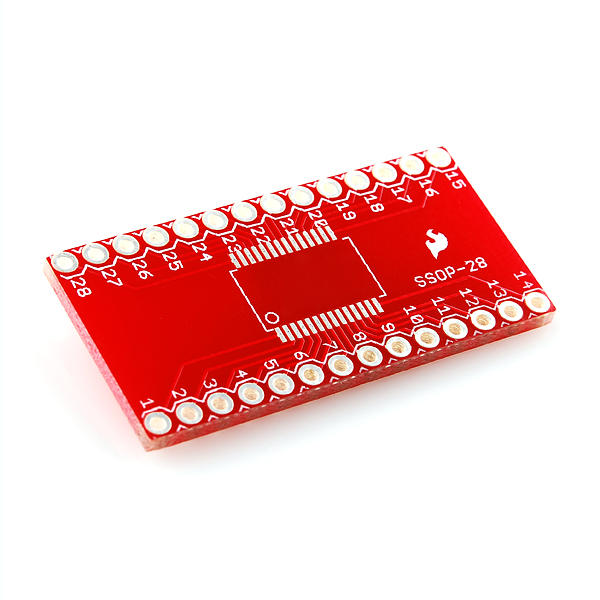
SparkFun SSOP to DIP Adapter - 28-Pin
8, 16, 20, and 28-Pin SSOP to DIP break out boards. The footprint was rotated to accommodate different width SSOP devices and can be used with any pin count up to 28 pins. Designed to be used with 0.65mm pitch devices but can also be used with 0.025" pitch devices (comes out to ~0.635mm). We've made these 0.635mm devices fit just fine. Can be used with packages that have a lead span of .230" up to .350".
40 Pin break-away headers are perfect for use with these custom PCBs. Machine pin headers may be a better option for IC sockets. Pad layout fits all standard SSOP .65mm and can accommodate .635mm pitch devices.
- 8-pin: 0.6 x 0.4" (15.24 x 10.16mm) 500mil DIP spacing
- 16-pin: 1.0 x 0.4" (25.4 x 10.16mm) 400mil DIP spacing
- 20-pin: 0.8 x 1.0" (20.32 x 25.4mm) 700mil DIP spacing
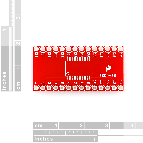
- 28-pin: 1.4 x 0.7" (35.56 x 17.78mm) 600mil DIP spacing.
- Schematic
- Eagle Files
- GitHub (Design Files)
SparkFun SSOP to DIP Adapter - 28-Pin Product Help and Resources
Core Skill: Soldering
This skill defines how difficult the soldering is on a particular product. It might be a couple simple solder joints, or require special reflow tools.
Skill Level: Competent - You will encounter surface mount components and basic SMD soldering techniques are required.
See all skill levels
Comments
Looking for answers to technical questions?
We welcome your comments and suggestions below. However, if you are looking for solutions to technical questions please see our Technical Assistance page.
Customer Reviews
5 out of 5
Based on 1 ratings:
My first experience with soldering surface mount devices. The key to successful soldering is have a solder mast right next to the pad to keep the solder from shorting out adjacent pins. The adapter is great and everything soldered without any problems!
The description and photo are somewhat inaccurate -- the boards I received are red and the IC footprint is in line rather than rotated. However the pin traces no longer go through to the underside of the board so there is nothing to short-out on a thermal pad.
Double check the width of your IC, many SSOP packages are less than 0.200" wide and unfortunately I can't use the boards I just ordered.
Ditto. I ended up hand soldering tiny wire strands to bridge the gap because I wanted to prototype a circuit and had no other breakouts on hand for SSOP.
A great revision to the board would be to accommodate the narrow SSOP form factor as well.
Dimension drawing please?
Does this breakout board work with TI's "PowerPAD" HTSSOP devices, which have an exposed thermal pad on the bottom? http://focus.ti.com/lit/ml/mhts001f/mhts001f.pdf
Hope you people understand you would get far fewer questions if you would just give real dimensions in real units on a real drawing. Are your Dimensions the package or the board? Do you know that in UK, Australia and India, "mil" is short for millimetre? After converting (because all modern chips are in metric), it does look as if my 6.4 mm package will fit in your .230 - .350 width. So buying some anyway, but with very low confidence it will fit.
any possibility we can get one in a 80 QFP? guess for the time being i'll have to etch my own.
any chance we could/will see this in a 24 pin model?
you can use a 24 pin IC on this board. You will just have unused pads.
Is this breakout board compatabile with pcm1680?
http://www.ti.com/lit/ds/symlink/pcm1680.pdf
Short answer: Yes.
Long answer: In the datasheet you mentioned, they mentioned that the package designation at TI is 'DBQ'. Hit Google with that and you should end up at the list of DBQ package dimensional drawings, and from there to the 28-pin package.
Open that datasheet. From the description of this product ". Designed to be used with 0.65mm pitch devices but can also be used with 0.025" pitch devices [...]". If you look at the top-left drawing, just below the bottom row of pins, it shows the pitch (the distance between 2 pins). It's indicated to be 0.025", so that matches this breakout board's spec.
Next up the description mentions "Can be used with packages that have a lead span of .230" up to .350". ". If you look again at the top-left drawing, all the way on the right, that shows the lead span (maximum distance between the very ends of the leads). It notes this as being between 0.228" and 0.244". So if you're very, very unlucky, the leads are actually 0.002" short. Just give the part a funny look or threaten to put it in a parts bin next to lowly transistors, and I'm sure it'll happily give you that 0.002". In other words.. that, too, is fine :)
Right here is an OUTSTANDING example of how to answer questions like this by finding and reading the datasheets. Well done sir!
would love this for a 32 pin HTSSOP. could I get the eagle file to modify it myself?
I'm unsure whether this thing is compatible with a chip I want to use, the MAXIM MAXQ3183. This chip comes in a TSSOP package and the pins reach 6.25-6.55 mm across. We are concerned that this breakout board has pads that are too far apart for our chip to reach. Can anybody help with this? I was referred to this product by the folks at NanoCore12.com when I inquired about a similar product.
Can we get Eagle Files?
the eagle library does not have a package for this part...
It's a standard 28-pin, 0.6" wide DIL socket. It's not in the SFE library, but it should be in ref-packages.lbr (supplied with Eagle) as DIL28-6. You could also use 2 x 14-pin 0.1" headers 0.6" apart.
The MAX7314 chips are between 230-244 mil from pin to pin and 150-157 mil body width. When I attempted to solder them to this board I discovered that I could only solder down one side of the chip, the other side would not reach. Its a bummer because the old green SSOP breakouts (that had the rotated chip placement) worked like a champ! I've emailed customer service about the issue so hopefully they can fix it in a new revision.
Heres a picture of the situation taken with my iPhone and a jewelers loupe. http://imgur.com/uT5GG
I'm having the same issue but with the FM radio chip. From the description it looked like they should fit. Detailed dimentional specs would have helped. This is the chip - SI4735-C40-GU AM/FM Radio IC
I am trying to do the same thing as you are describing with the SI4735 AM/FM radio IC. What did you end up doing?
Not much can be done about the carrier board, I used eagle to make an appropriate pattern for the chip . Hope this helps.
From my experience it seems the 0.2" (5mm) is the package width excluding the leads. 3.9mm did not fit.
Is the package width (minimum 0.2") from the outside of the pins to outside of pins, or just the actual package (excluding pins)?
Or, more helpful, does it work with the A3941?
Please email tech support directly at techsupport@sparkfun.com
These are PERFECT for the FTDI USB chips FT232RL