- Home
- Product Categories
- 7-Segment
- 7-Segment Display - 4-Digit (Red)

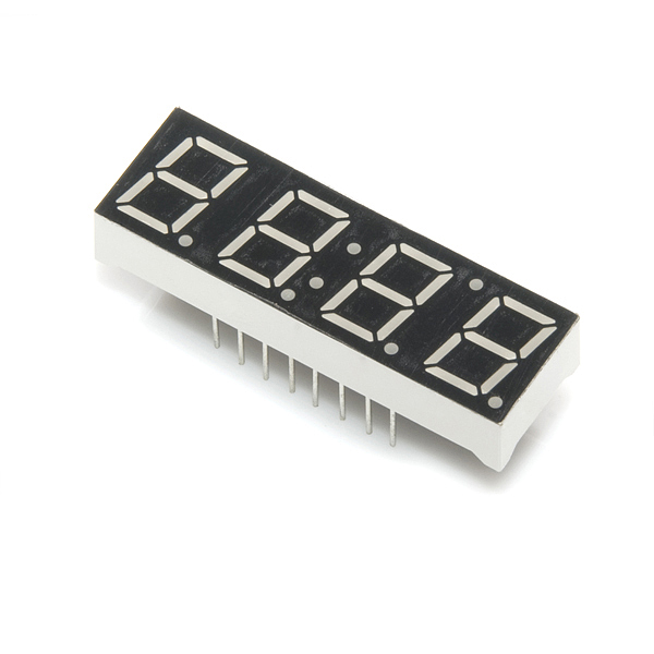
This is a basic, 4-digit 7-segment display - red in color. It has a common anode. The display features one decimal point per digit, and individually controllable apostrophe and colon points.
The LEDs have a forward voltage of 2.1VDC and a max forward current of 20mA. The hardware interface is sixteen (two rows of eight) through-hole pins.
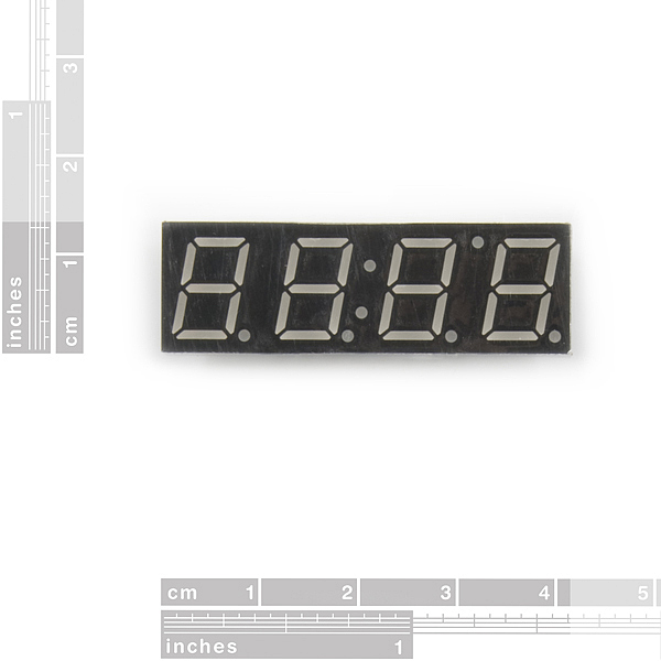
- Overall Display: 40.18 x 12.8 mm (1.58 x 0.50")
- Digit Height: 10mm (0.39")
7-Segment Display - 4-Digit (Red) Product Help and Resources
Core Skill: Electrical Prototyping
If it requires power, you need to know how much, what all the pins do, and how to hook it up. You may need to reference datasheets, schematics, and know the ins and outs of electronics.
Skill Level: Competent - You will be required to reference a datasheet or schematic to know how to use a component. Your knowledge of a datasheet will only require basic features like power requirements, pinouts, or communications type. Also, you may need a power supply that?s greater than 12V or more than 1A worth of current.
See all skill levels
Comments
Looking for answers to technical questions?
We welcome your comments and suggestions below. However, if you are looking for solutions to technical questions please see our Technical Assistance page.
Customer Reviews
No reviews yet.
I have an i2c interface but I don't know how to connect the 4 digit seven segment display to it. I would be glad if you can help
You can't use this display directly with I2C since it doesn't have a controller built in. It's just a bunch of LEDs arranged to make four digits. If you want I2C control, our 7-Segment Serial Display is what you want. It has a controller built in that lets you use I2C, SPI or TTL serial.
For a newbie like me these were tricky to figure out...
In other examples I saw people put the digit they want to display high and then the A-G parts they wanted to display high also. But that doesn't work for this display.
The digit to display must be set to high.
But you can either set the A-G parts to low or to toggle them between input and output (where input means on) to display them.
The whole knowing where the flow of electrons goes when using these displays can be very mind boggling at times...
Sorry, I meant to say: (where OUTPUT means on)
Mr. JLC,
I was unable to find any examples online of this display being used. I just received a blue (3.4 VDC) and a yellow (2.1 VDC) one of these. I'm not sure how to go about hooking them up to an arduino.
I think the answer lies in your post above, but being the n00b that i am, i'm still unsure about what to do. Can you please describe in more detail or provide some sample code? how do i vary the voltage depending on the 2.1 V or 3.4 V version?
Thanks in advance!
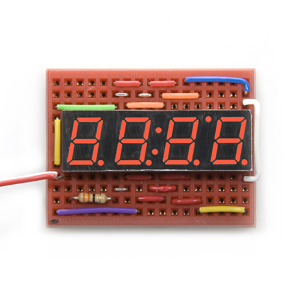
I posted a tutorial with pictures, a schematic and two coding examples for anyone who is new to these displays. Arduino 4 Digit 7 Segment LED Display Circuit and Code
These are common anode displays, therefore you have to pull the A-G pins low to turn them on.
Looks like the easiest way to use this with arduino is https://github.com/sparkfun/SevSeg
what is the lead diameter on these things for PCB layout? Didn't see it in the spec . . .
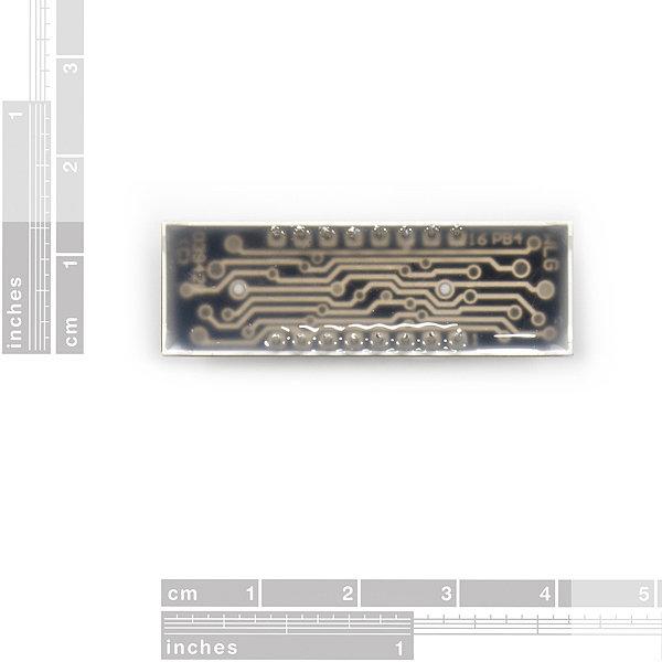
maybe i'm blind, but I cannot find an explanation of what pin is what for the life of me! I understand that of the 16 pins, 8 are the 7segments abcdef+decimal, 4 are the digits, 1 is the colon, and 1 is for ground i guess? but which pin is what! if anyone could direct me to an image that made this clear i would really appreciate it!
It's tricky to see, but if you look at the back of the display, through the clear epoxy, to the little circuit board within, you should be able to make out a "1" by pin 1, and a "16" by pin 16. These follow the normal IC numbering convention of increasing counterclockwise when viewed from the top of the device. Once you know the numbers, the datasheet has a diagram showing which pins go to which segments. Let us know if you need further assistance!
Any idea when these will be back in stock?
How do i control different digits displaying different things? I can only have the light up digits say the same thing.
Turn all digits off
In a loop :
Turn the first digit on
Turn on segments
Turn all segments off
Turn first digit off
Repeat for other digits
Micros do this so fast you cant even tell when they are off so you'll see all the digits on with diferent numbers.
I made a project on instructables with this display http://www.instructables.com/id/TimeDuino-Arduino-based-clock-using-7-segment-dis/
One of the LEDs on mine doesn't work.
I contacted support, they sent me a new one. :)
Did you try lumos?
Look for a multiple-digit LED display driver chip to make driving these easy. Maxim makes the MAX7219 and MAX7221 that do this (http://www.maxim-ic.com/quick_view2.cfm/qv_pk/1339).
oops, just realized these are common-anode. So the ICM7218 or ICM7228 may be better even though the maxim chips have more functionality.
I've used an ICM7218A as IsotopeJ suggested and it works fine.
And combined with a PCF8574 you only need 2 pins from the Arduino to control 2 displays.
I hope next week I'll be able to make a post with the how-to and source code. Meanwhile, here is a video: http://www.youtube.com/user/ardugoblog#p/a/u/0/iO3DRslhQK0
If you want to control more than 1 display, using an ICM7218 you'll need 10 pins from your microcontroller. Using I2C you can reduce the amount to only 2 pins for all the displays you want to control. I've written a post about it (with source code for Arduino): http://ardugonic.blogspot.com/2010/06/icm7218a-combined-with-pcf8574-to.html
And here is the post: http://ardugonic.blogspot.com/2010/05/driving-8-digits-7-segment-display-with.html
I have posted my code and so have a few others on my arduino forum topic here:
http://www.arduino.cc/cgi-bin/yabb2/YaBB.pl?num=1265669651