SparkFun Qwiic Button Hookup Guide
 El Duderino
 Introduction
Buttons are a great way to add a tactile input to your project but dealing with pull-up resistors, debouncing, polling, and using GPIO pins for each button can be a hassle. Enter the Qwiic Button (Red or Green) and the Qwiic Button Breakout! These breakouts eliminate nearly all the inconvenience of using buttons by converting everything to an easy-to-use I2C connection using the Qwiic Interface.
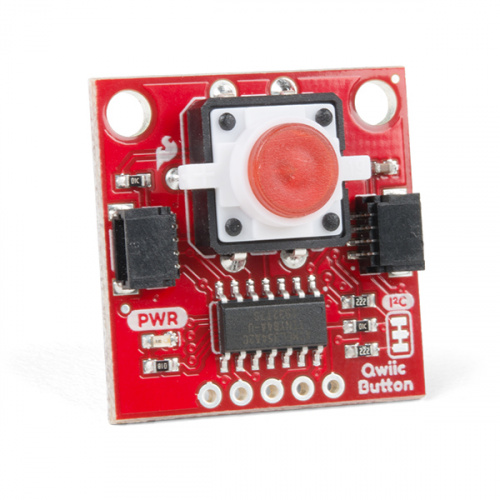
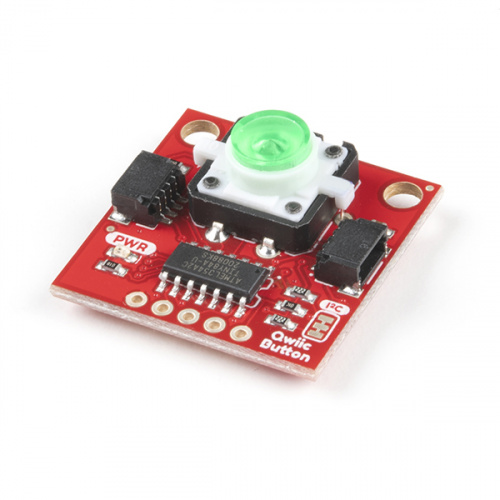
We have three versions of the Qwiic Button available. The Qwiic Button (Red) and Qwiic Button (Green) come with a pre-populated red or green pushbutton with a built in LED to illuminate the button and the Qwiic Button Breakout leaves the button unpopulated so you can choose your own tactile button.
Using the Qwiic Button is as simple as sending the command button.isPressed() to check the status of the button. In addition to handling status checks and debouncing, the Qwiic Button has a configurable interrupt pin which can be adjusted to activate upon a button press or click. This allows you to trigger specific behavior or functions in your code when the button is used and frees up processing time that would normally be used to constantly poll a button's state.
The Qwiic Button also includes a First-in First-Out (FIFO Queue) which keeps track of when the button was pressed so if you are hosting a game show you can easily keep track of which contestant pressed their button first without needing to constantly poll the buttons!
Required Materials
The Qwiic Button requires a Qwiic-enabled microcontroller:


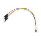
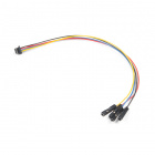
And you will also need a Qwiic cable:


Or, if you want to use a microcontroller without a Qwiic connector, you can add one using one of our Qwiic Shields, the Qwiic Adapter board, or adapter cables:


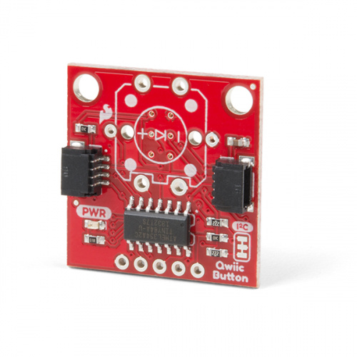
Finally, if you are using the Qwiic Button Breakout you'll need to solder a button to the board:
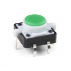

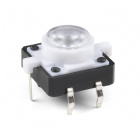
Realistically, you can solder any pushbutton to the Qwiic Button Breakout so long as it fits the button footprint. We have a couple other options available in our Button Category that will work perfectly with the Qwiic Button Breakout.


Suggested Reading
If you aren't familiar with the Qwiic system, we recommend reading here for an overview:
| Qwiic Connect System |
We would also recommend taking a look at the following tutorials if you aren't familiar with them.
Button and Switch Basics
Processor Interrupts with Arduino
Qwiic Shield for Arduino & Photon Hookup Guide
Hardware Overview
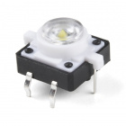
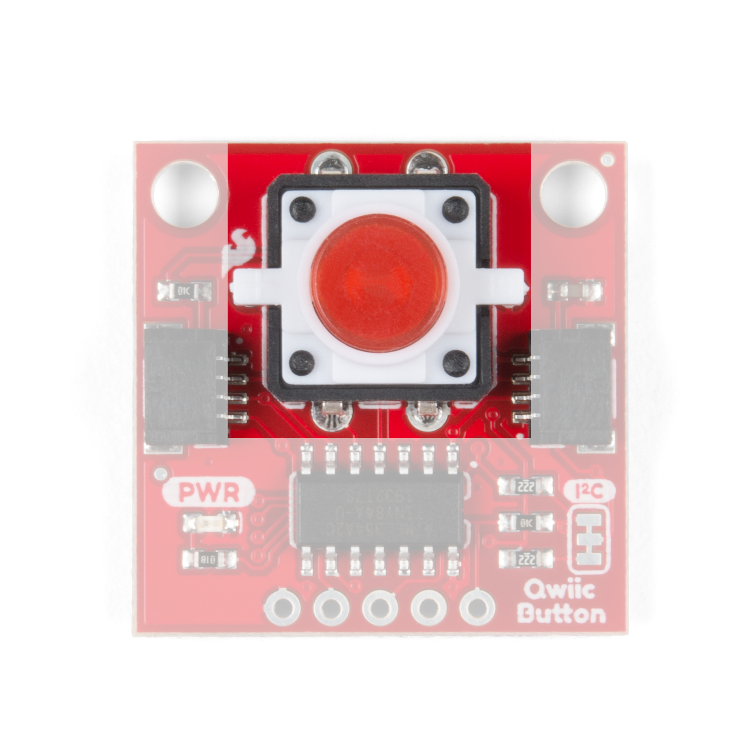
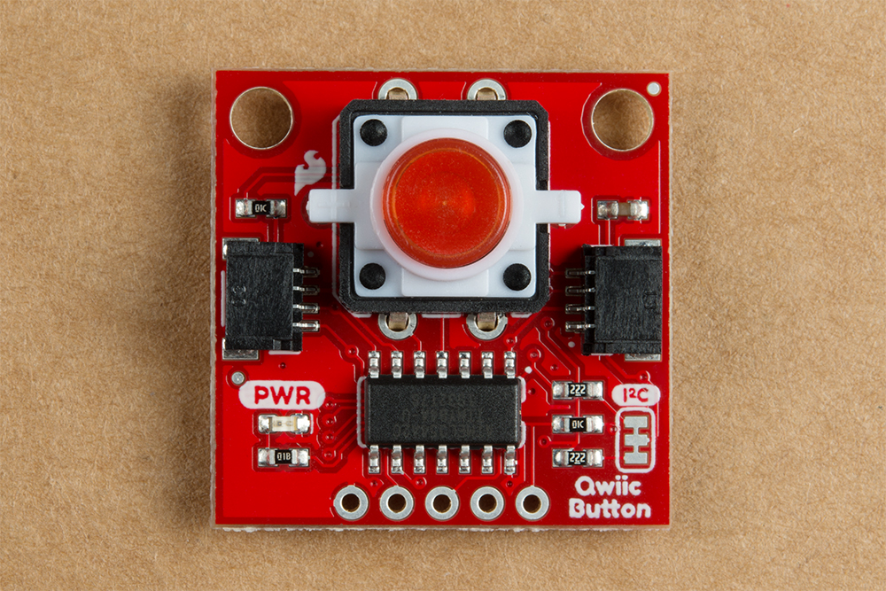
Tactile Button
This is a standard pushbutton with a built in red or green LED depending in which version you have. The LED's anode (positive pin) is connected to an I/O pin on the ATtiny84 so you can turn it on and off as well as control the brightness. If you have the Qwiic Button Breakout, you can choose your own color of button from the selection listed in the Introduction of this guide or any tactile button that fits the footprint on the breakout.
 |
 |
| Red Tactile Button | Button Footprint |
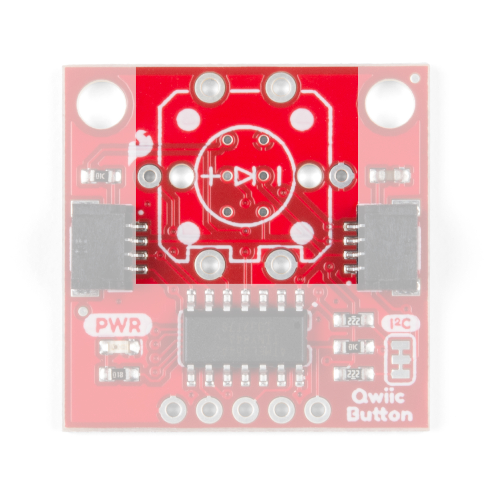
Qwiic and I2C Interface
The easiest way to use the Qwiic Button is with the Qwiic connect system. Simply plug in a Qwiic Cable to start talking to it.
 |
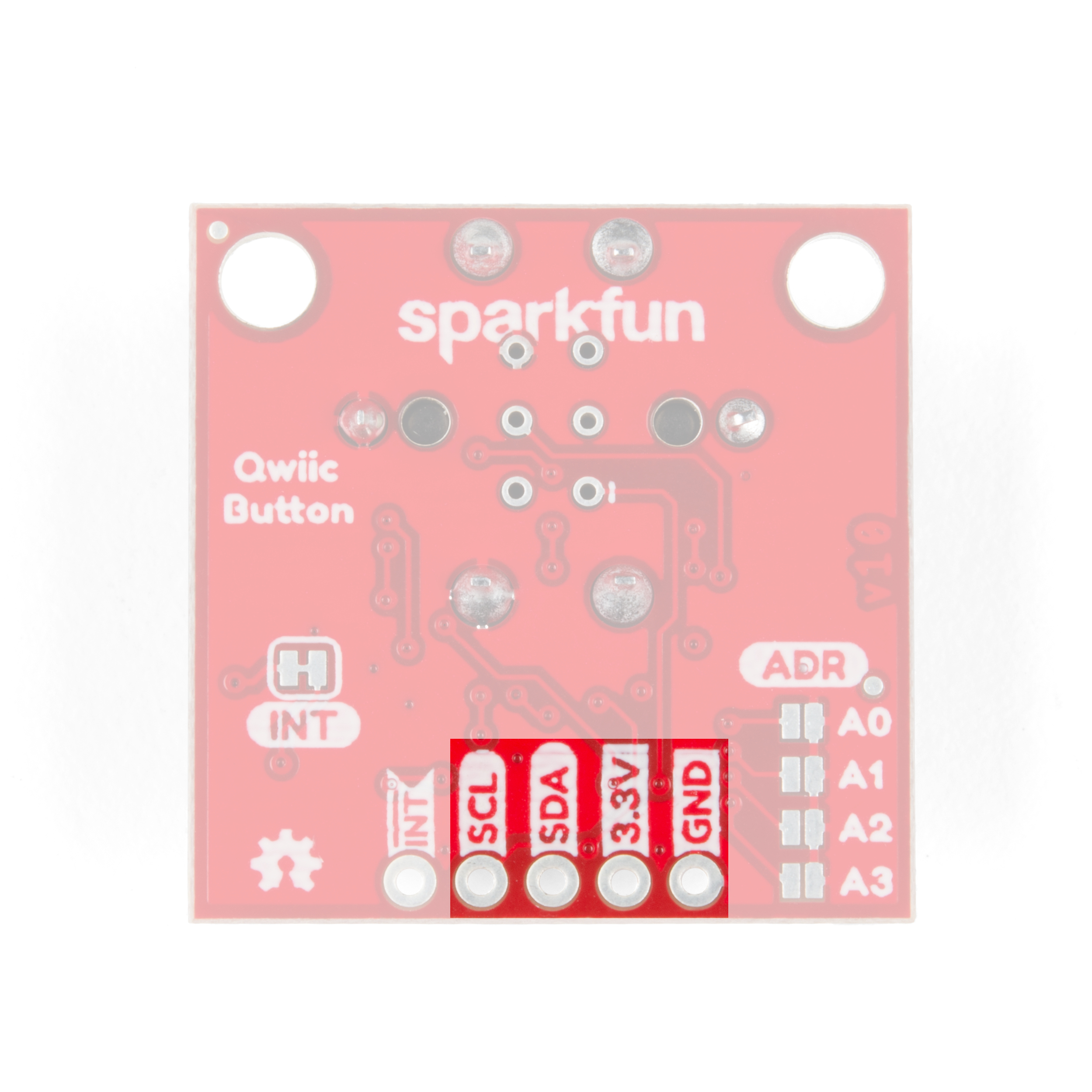 |
| Qwiic Connectors | I2C Pins |
Alternatively, you can solder to the I2C pins broken out on the board.
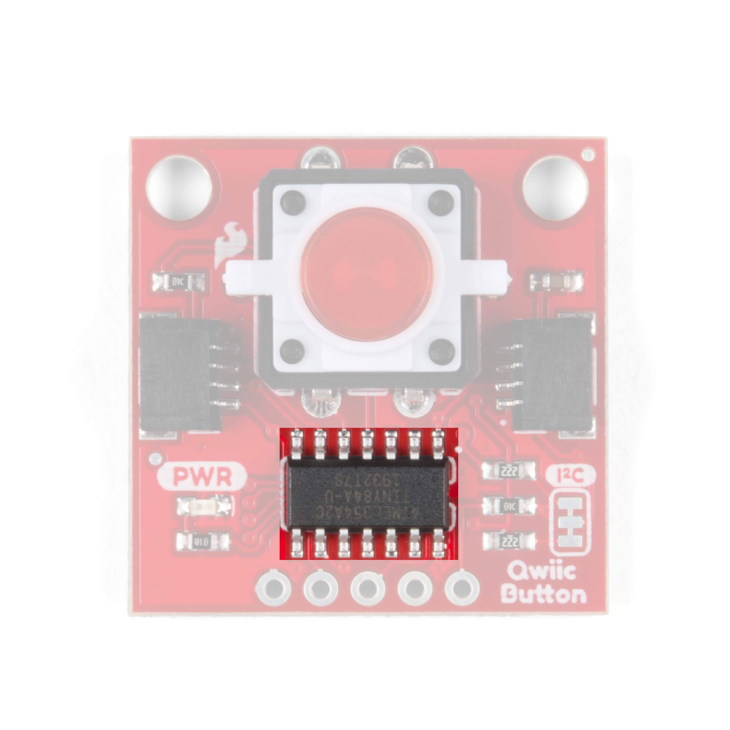
ATtiny84
The ATtiny84 has pre-installed firmware to handle the various functions of the Qwiic Button. It acts as an intermediary device to send and receive I2C data for things like button presses, clicks, the FIFO queue and it allows you to set a custom I2C address for the Qwiic Button. If you would like, you can modify the firmware on the Qwiic Button using the 2x3 pins on the back of the board. The firmware can be found in the Hardware GitHub Repository and if you need help programming the ATTiny84, check out this tutorial.
Jumpers
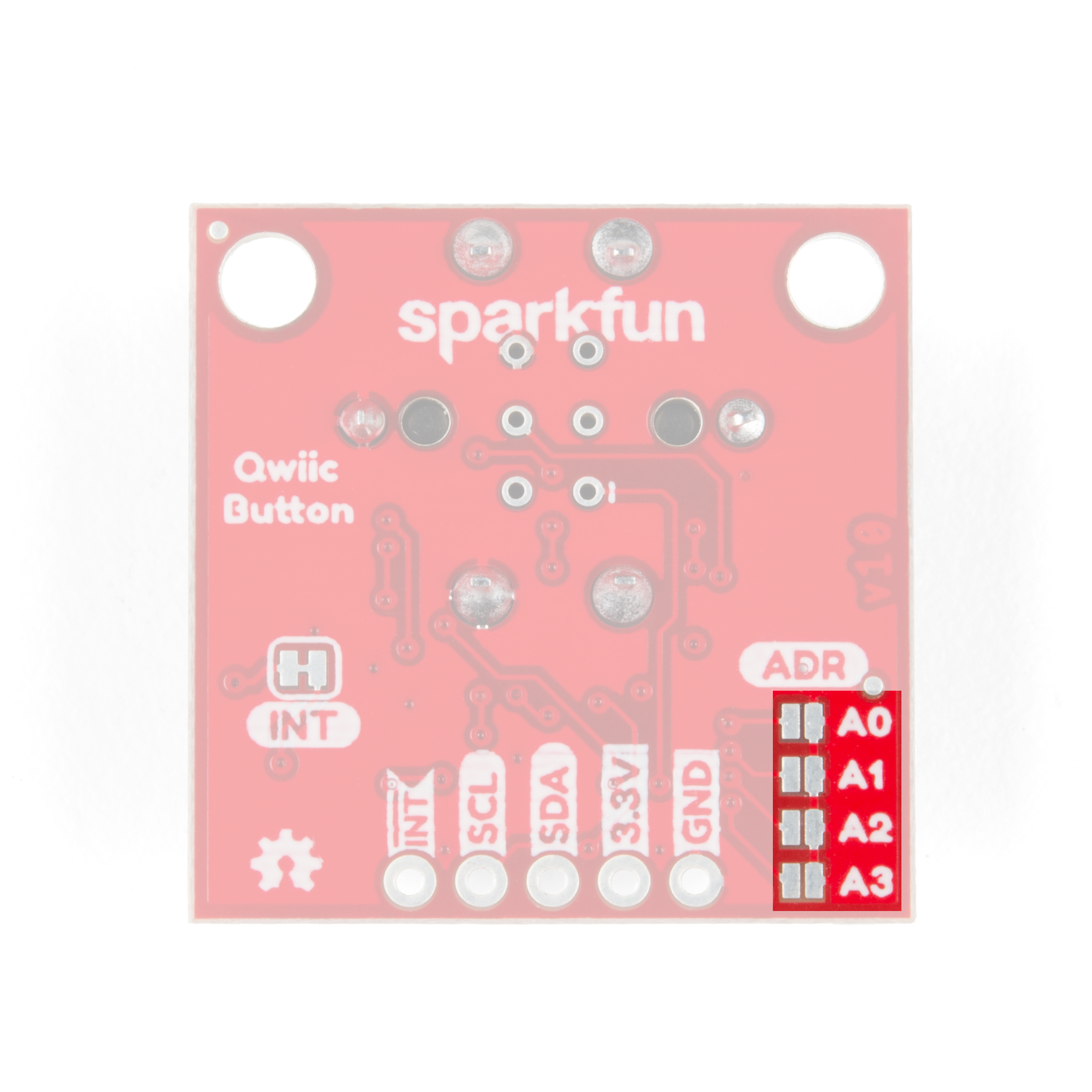
I2C Address Jumpers
There are four solder jumpers on the board (labeled A0, A1, A2 and A3) you can close to set the I2C address. The firmware reads the logic of each address pin so, by closing multiple jumpers, you can modify the Qwiic Button with up to sixteen unique addresses! If you do not want to use the address pins, the address can also be configured using the ChangeI2CAddress Example from our Arduino Library.
- All Open: Factory or User Set I2C Address: 0x6F (Factory Set) or 0x## (User Set)
- Alternate Address Jumpers: Closing an address jumper sets the pin LOW. On boot-up, the firmware checks the state of these four pins and adjusts the I2C address following this logic:
0b0110,A3,A2,A1,A0For example, with both A0 and A1 jumpers closed, (A0 = 0, A1 = 0, A2 = 1, A3 = 1) the I2C address of the Qwiic Button is set to 0x6C (0b01101100). Check out the table below for a full list of all the I2C addresses and the jumper logic used to set the address.
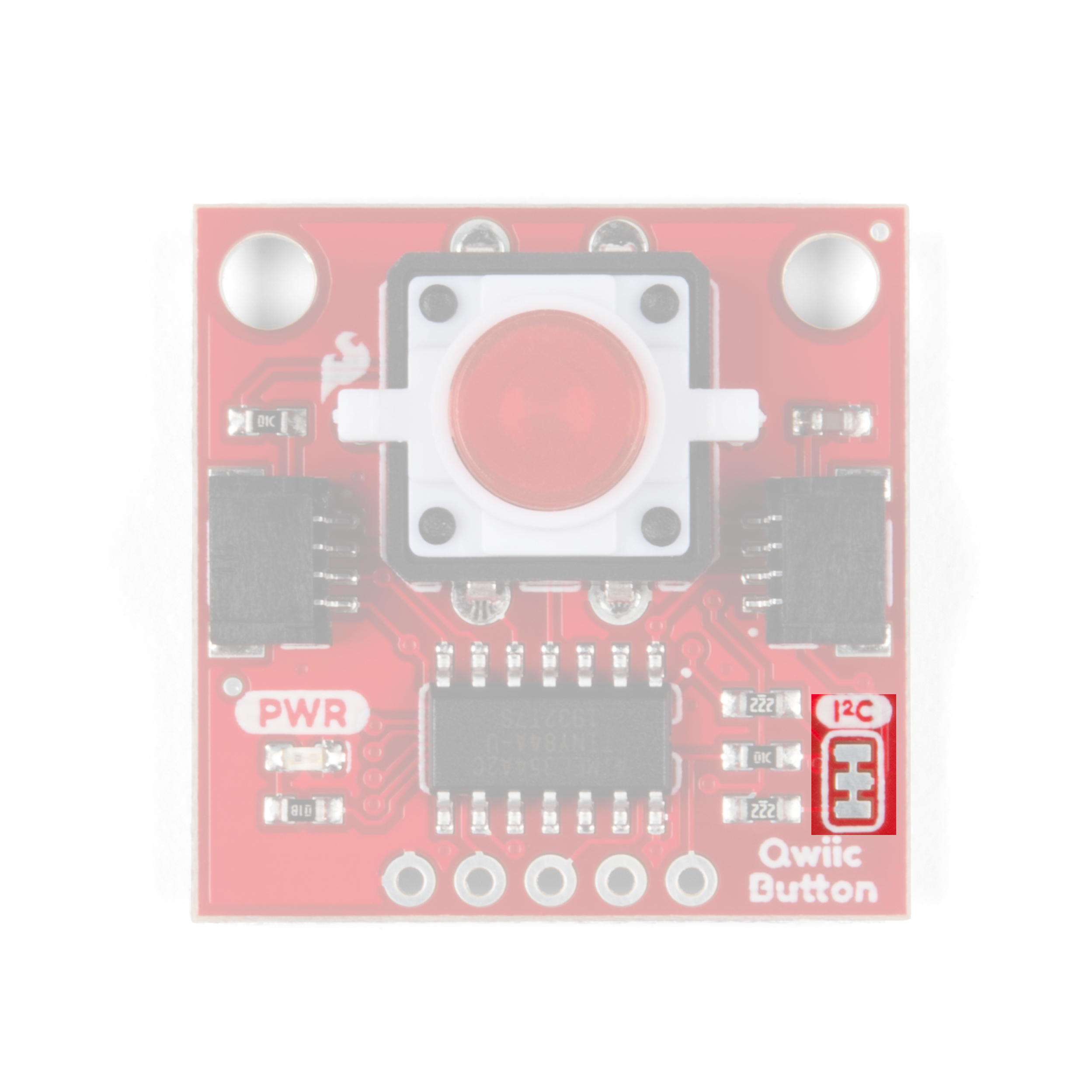
I2C Pull-Up Resistors
Severing the trace on the I2C jumper will remove the 2.2kΩ pull-up resistors from the I2C bus. If you have many devices on your I2C bus you may want to open these jumpers by severing the trace in between the pads.
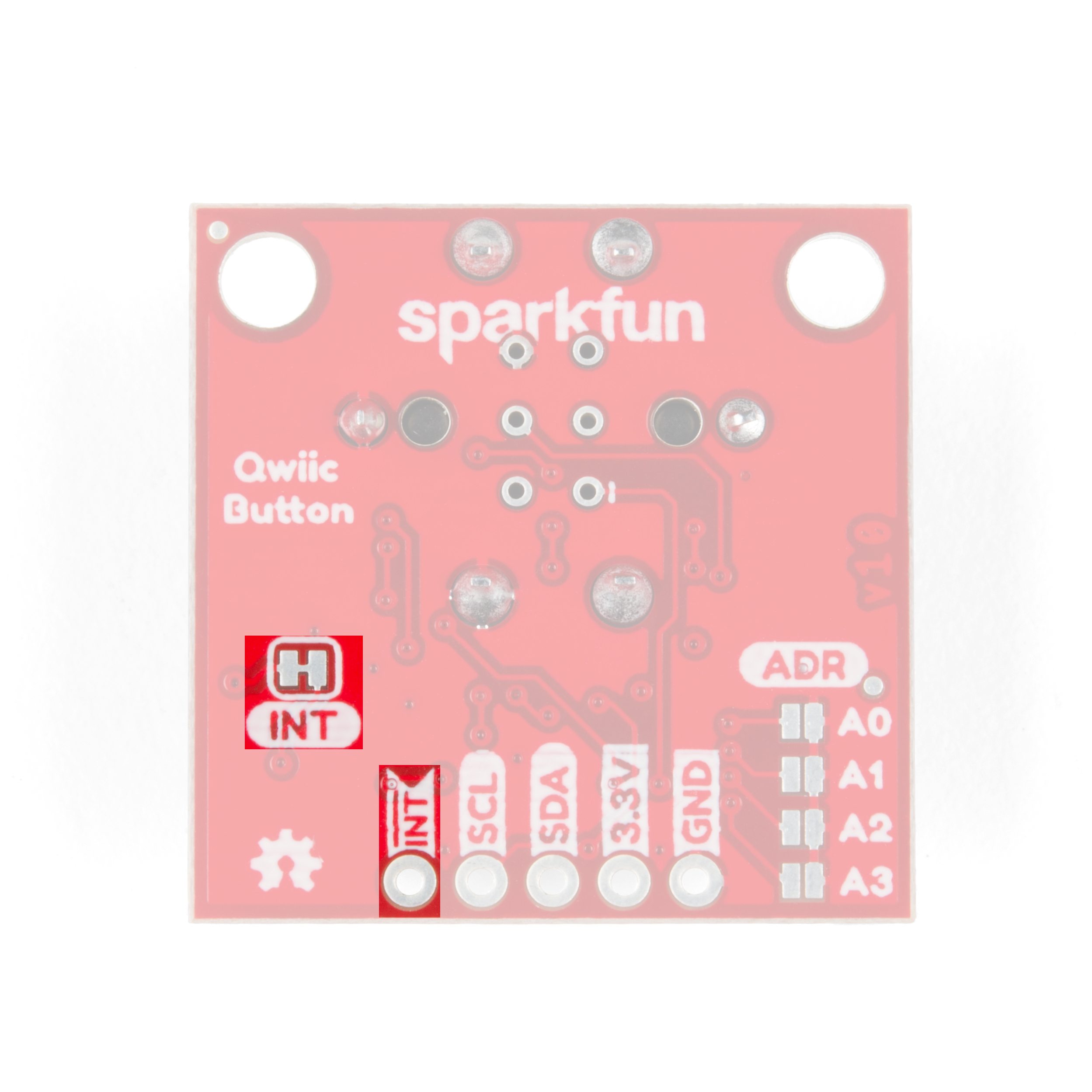
Interrupt Pin
The Interrupt Pin can be used to trigger events on your microcontroller. It is active LOW and can be configured to activate on either a button press (held down) and click (press-and-release). By default, the Interrupt Pin is pulled to 3.3V via a 10K resistor through this jumper. Just like the I2C pull-up resistors, you can open it by severing the trace in between the pads. This may come in handy for low-power projects that do not require the Interrupt Pin.
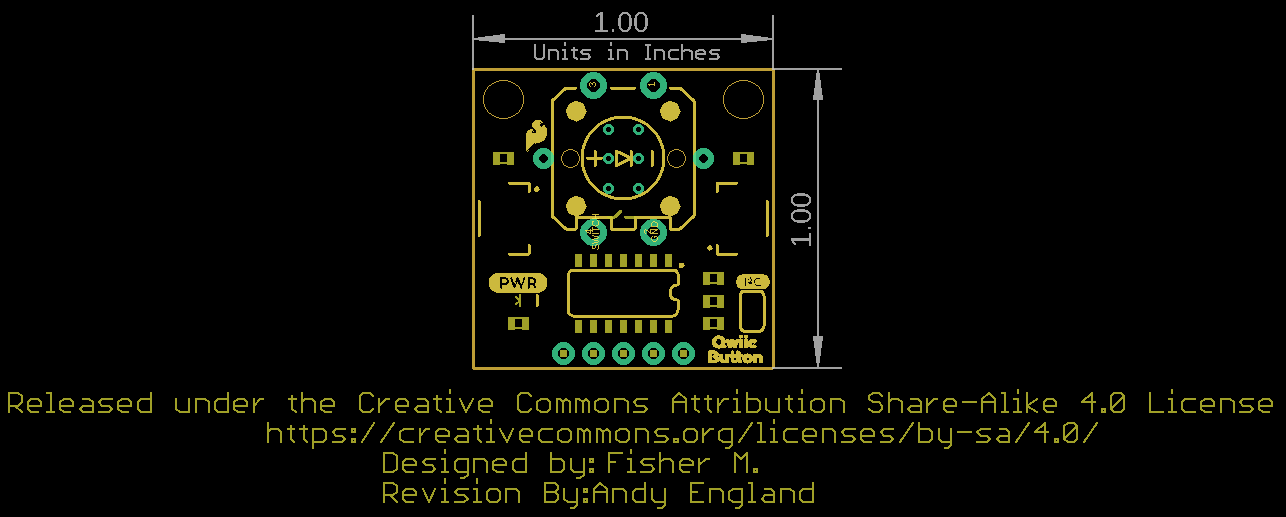
Board Dimensions
The breakout board is the standard Qwiic size of 1" x 1" and has two mounting holes that fit a standard 4-40 screw.
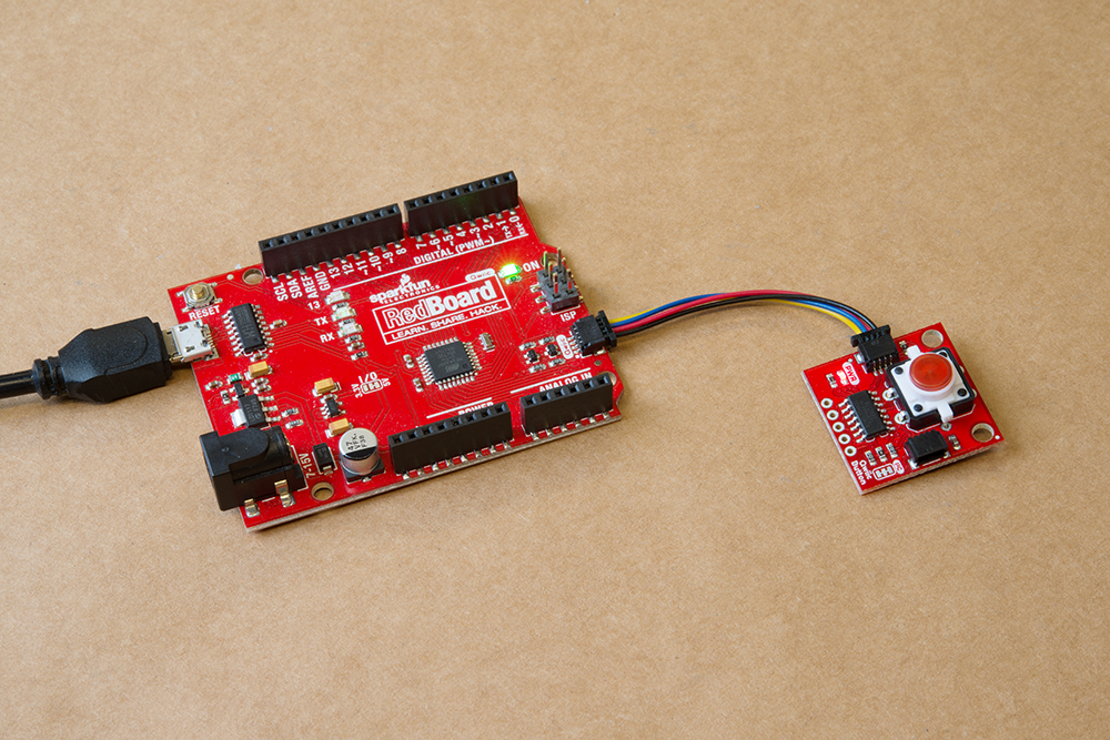
Hardware Assembly
With the Qwiic connector system, assembling the hardware is simple. All you need to do is connect your Qwiic Button to Qwiic-enabled microcontroller with a Qwiic cable. Otherwise, you can use the I2C pins if you don't have a Qwiic connector on your microcontroller board. Just be aware of your input voltage and any logic level shifting you may need to do since the Qwiic system runs at 3.3V.
If you have the Qwiic Button Breakout, you will need to solder a button into place. If you are using a Tactile Button with an integrated LED, remember to pay close attention to the polarity marks on your button and match them to the markings on the top of the Qwiic Button Breakout. If you purchased a tactile button from SparkFun, the anode will be marked with a small "+" on the top of the button.
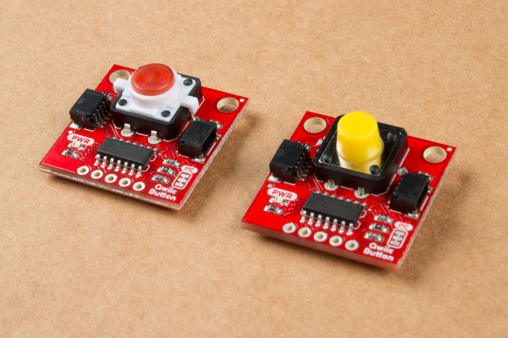
Once your button(s) are soldered into place and you're certain all pins are well connected, you're ready to go! The image below shows two of the several options for buttons on the Qwiic Button. One is the standard Red LED Tactile Button and the other is from our Multicolor Button 4-Pack:
Qwiic Button Arduino Library
The easiest way to install the library is to search for SparkFun Qwiic Button in the Arduino Library Manager tool. You can also manually install the Qwiic Button Library from the GitHub Repository or you can download it by clicking the button below.
Library Functions
Here is a list of the functions of the library with some quick descriptions of what they do. The examples cover most of the functions so we recommend going through them first.
Device Status
begin(uint8_t address = DEFAULT_ADDRESS, TwoWire &wirePort = Wire);- Sets device I2C address to a user-specified address, over whatever port the user specifies.isConnected();- Returns true if the button will acknowledge over I2C, false otherwise.uint8_t deviceID();- Return the 8-bit device ID of the attached device.checkDeviceID();- Returns true if the device ID matches that of either the button or the switchuint8_t getDeviceType();- Returns 1 if a button is attached, 2 if a switch is attached. Returns 0 if there is no device attached.uint16_t getFirmwareVersion();- Returns the firmware version of the attached device as a 16-bit integer. The leftmost (high) byte is the major revision. The rightmost (low) byte is the minor version number. (Ex. 0x0202 is v2.02)setI2Caddress(uint8_t address);- Configures the attached device to attach to the I2C bus using the specified address.uint8_t getI2Caddress();- Returns the I2C address of the device.
Button Status/Configuration
isPressed();- Returns 1 if the button is pressed, and 0 otherwise.hasBeenClicked();- Returns 1 if the button was clicked, and 0 otherwise.uint8_t setDebounceTime(uint16_t time);- Sets the time that the button waits for the mechanical contacts to settle (in ms) and checks if the register was set properly. Returns 0 on success, 1 on register I2C write fail, and 2 if the value didn't get written into the register properly.uint16_t getDebounceTime();- Returns the value set to wait for the button's the mechanical contacts to settle, (in ms).
isPressed(); and hasBeenClicked();. The isPressed(); function returns true while the button is pressed/held down and false when the button is unpressed/released. The hasBeenClicked(); function will only return true when the button is pressed and then released. Interrupt Status/Configuration
uint8_t enablePressedInterrupt();- Configure the interrupt pin to go LOW while the button is pressed (held down).uint8_t disablePressedInterrupt();- Sets the interrupt to no longer trigger while the button is pressed.uint8_t enableClickedInterrupt();- Configure the interrupt pin to go LOW when the button is clicked.uint8_t disableClickedInterrupt();- Configures the interrupt pin to no longer go low when the button is clicked.uint8_t clearEventBits();- Sets "isPressed", "hasBeenClicked", and "eventAvailable" to zero.uint8_t resetInterruptConfig();- Resets all interrupt configuration settings back to defaults.
FIFO Queue
isPressedQueueFull();- Checks the queue of button press timestamps and returns true if full, false otherwise.isPressedQueueEmpty();- Opposite of the above function. Checks if the timestamp queue is empty.unsigned long timeSinceLastPress();- Returns the time (in ms) since the last button press.unsigned long timeSinceFirstPress();- Returns time (in ms) since the first button press.popPressedQueue();- Returns the oldest value in the Pressed Queue (ms since first button press), and then removes it.isClickedQueueFull();- Checks the queue of button click timestamps and returns true if full, false otherwise.isClickedQueueEmpty();- Opposite of the above function. Checks if the timestamp queue is empty.unsigned long timeSinceLastClick();- Returns the time (in ms) since the last button click.unsigned long timeSinceFirstClick();- Returns the time (in ms) since the first button click.popClickedQueue();- Returns the oldest value in the Clicked Queue (ms since first button click), and then removes it.
Button LED Configuration
LEDoff();- Turn the button LED off.LEDon(uint8_t brightness = 255);- Turn the button LED on and set the brightness.LEDconfig(uint8_t brightness, uint16_t cycleTime, uint16_t offTime, uint8_t granularity = 1);- Configures the button LED.- Brightness: Stores the brightness of the LED. Accepts values between 0 and 255.
- cycleTime: Total pulse cycle time (in ms). Does not include off time.
- offTime: Off time between pulses (in ms). Default is 500 ms.
- granularity: Amount of steps it takes to get to the set brightness level.
Internal I2C Abstraction
uint8_t readSingleRegister(Qwiic_Button_Register reg);- Reads a single 8-bit register.uint16_t readDoubleRegister(Qwiic_Button_Register reg);- Reads a 16-bit register (little endian).unsigned long readQuadRegister(Qwiic_Button_Register reg);- Reads a 32-bit register (little endian).writeSingleRegister(Qwiic_Button_Register reg, uint8_t data);- Attempts to write data into a single 8-bit register. Does not check to make sure it was written successfully. Returns 0 if there was no error on I2C transmission, and 1 otherwise.writeDoubleRegister(Qwiic_Button_Register reg, uint16_t data);- Attempts to write data into a double (two 8-bit) registers. Does not check to make sure it was written successfully. Returns 0 if there was no error on I2C transmission, and 1 otherwise.uint8_t writeSingleRegisterWithReadback(Qwiic_Button_Register reg, uint8_t data);- Writes data into a single 8-bit register, and checks to make sure the data was written successfully. Returns 0 on no error, 1 on I2C write fail, and 2 if the register doesn't read back the same value that was written.uint16_t writeDoubleRegisterWithReadback(Qwiic_Button_Register reg, uint16_t data);- Writes data into a double (two 8-bit) registers, and checks to make sure the data was written successfully. Returns 0 on no error, 1 on I2C write fail, and 2 if the register doesn't read back the same value that was written.
Arduino Examples
In this section we will go over a few of the examples from our Qwiic Button Arduino Library. Here is a full list of all the examples included in the library:
- Example 1 - Prints the button status.
- Example 2 - Turns the button LED on while the button is pressed.
- Example 3 - Pulses the button LED while the button is pressed.
- Example 4 - Demonstrates how to use the FIFO Queue and returns time elapsed since button presses.
- Example 5 - Details how to identify and change the I2C address.
- Example 6 - I2C Bus Configuration. Useful for devices with multiple I2C ports.
- Example 7 - Sets up 2 Qwiic Buttons and reads their statuses.
- Example 8 - Configures the button to toggle the interrupt pin when pressed.
Example 1: Print Button Status
The code for Example1_PrintButtonStatus connects the Qwiic Button to the I2C bus and prints the status of the button (pressed or not pressed) to the Serial Monitor.
Example 3 Pulse When Pressed
Example3_PulseWhenPressed connects the Qwiic Button to the I2C bus and runs the Button LED through a configured sequence when the button is pressed. The code configures the LED settings for brightness, cycleTime and offTime to pulse the Button LED while it is pressed. Try playing around with these settings to change the behavior of the LED.
Example 4 Queue Usage
Example4_QueueUsage demonstrates how to call, check, and alter the FIFO Queue for a button press and button click. The code will check both the Pressed and Clicked queues and, if the queue is not empty, prints over serial the time since the first press (since the queue was last cleared) and the time since the last press. Entering "P" in the serial monitor will "pop" the Pressed Queue to return the oldest value stored in the queue and then remove it. Entering "C" will perform the same action for the Clicked Queue.
Example 5 Change I2C Address
Example5_ChangeI2CAddress checks to initialize the Qwiic Button on the I2C bus. If the device ID matches what is expected (0x6F by default), it then will print some helpful information for changing the I2C address and prompt you for an input to change the address. Once a new device ID is input and is valid, the code writes the new I2C address to EEPROM on the ATtiny84 and prints out a success note along with the new device ID. If the entered address is invalid or for some reason the write fails, the code will print out an error detailing what failed.
If the device ID does not match what is expected, it runs a scan for devices on the bus and prints out the ID of any attached device. Make sure to set up the Serial Monitor for the correct baud rate and enable both Newline and Carriage Return. Also, do not enter the "0x" prefix. For example, you want to set the address to "0x5B", type in "5B" and press enter. The gif below shows the serial printout of a successful initialization and device address change to 0x5B:
button.begin(); function to include the alternate address. For example, if the new address is 0x5B, your begin function should look like this: button.begin(0x5B);Example 8 External Interrupt
Example8_ExtInterrupt demonstrates how to use the external interrupt pin to trigger an event on an attached microcontroller. You will want to solder to the INT pin and connect it to an interrupt-capable pin. If you just need to quickly prototype a circuit using the INT pin on the Qwiic Button, you can connect to it using something like these IC Hooks. The photo below demonstrates how to use the IC Hook for a temporary connection.
The code initializes the Qwiic Button on the I2C bus, attaches an interrupt to the selected pin (D2 by default), and configures the interrupt function for any button event (pressed or clicked). The INT pin will go LOW whenever a button event is registered and the selected interrupt pin on the microcontroller will fire whenever it sees a FALLING edge (going from HIGH to LOW). If you want to see it in action, you could attach an LED to the selected interrupt pin or you can modify the code to toggle all sorts of functions whenever the interrupt pin goes LOW.
int interruptPin = 2; call to the appropriate I/O pin.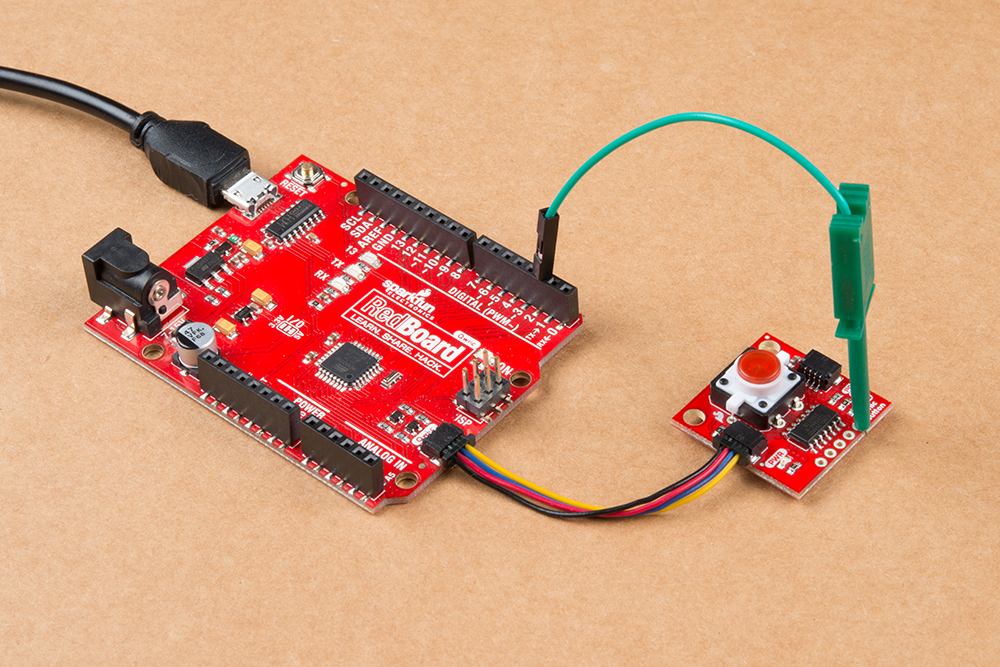
Register Map
If you would like to use a different development environment than Arduino, you can use the register map below to communicate with the Qwiic Button.

The Qwiic Button behaves as a normal I2C device. First write the address of the register you would like to read or write, then follow that I2C command with a Read to read the given register or a Write and a data byte to write to a register.
Python Package
Note: This tutorial assumes you are using the latest version of Python 3. If this is your first time using Python or I2C hardware on a Raspberry Pi, please checkout our tutorial on Python Programming with the Raspberry Pi and the Raspberry Pi SPI and I2C Tutorial. Jetson Nano users can check out this tutorial on Working with Qwiic on a Jetson Nano through Jupyter Notebooks.
We've written a Python package to easily get setup and use the Qwiic Button. There are two methods for installing the Python package for the Qwiic Button.
- Install the all inclusive SparkFun Qwiic Python package.
- Independently install the SparkFun Button Python package.
The all inclusive SparkFun Qwiic Python package, is recommended as is also installs the required I2C driver as well.
Note: Don't forget to double check that the hardware I2C connection is enabled on your single board computer.
SparkFun Qwiic Package
This repository is hosted on PyPi as the sparkfun-qwiic package. On systems that support PyPi installation via pip3 (use pip for Python 2) is simple, using the following commands:
For all users (note: the user must have sudo privileges):
language:bash
sudo pip3 install sparkfun-qwiic
For the current user:
language:bash
pip3 install sparkfun-qwiic
Independent Installation
You can install the sparkfun-qwiic-button Python package independently, which is hosted by PyPi. However, if you prefer to manually download and install the package from the GitHub repository, you can grab them here (*Please be aware of any package dependencies. You can also check out the repository documentation page, hosted on ReadtheDocs.):
PyPi Installation
This repository is hosted on PyPi as the sparkfun-qwiic-button package. On systems that support PyPi installation via pip3 (use pip for Python 2) is simple, using the following commands:
For all users (note: the user must have sudo privileges):
language:bash
sudo pip3 install sparkfun-qwiic-button
For the current user:
language:bash
pip3 install sparkfun-qwiic-button
Local Installation
To install, make sure the setuptools package is installed on the system.
Direct installation at the command line (use python for Python 2):
language:bash
python3 setup.py install
To build a package for use with pip3:
language:bash
python3 setup.py sdist
A package file is built and placed in a subdirectory called dist. This package file can be installed using pip3.
language:bash
cd dist
pip3 install sparkfun_qwiic_button-<version>.tar.gz
Python Package Operation
Before we jump into getting readings, let's take a closer look at the available functions in the Python package. Below, is a description of the basic functionality of the Python package. This includes the package organization, built-in methods, and their inputs and/or outputs. For more details on how the Python package works, check out the source code and package documentation.
Dependencies
This Python package has a very few dependencies in the code, listed below:
language:python
import qwiic_i2c
import math
Default Variables
The default variables, in the code, for this Python package are listed below:
language:python
# qwiic_button GLOBAL VARIABLES
#----------------------------------------------------------------------------------------------------
# Define the device name and I2C addresses. These are set in the class defintion
# as class variables, making them avilable without having to create a class instance.
# This allows higher level logic to rapidly create a index of qwiic devices at
# runtine
#
# The name of this device
_DEFAULT_NAME = "Qwiic Button"

# Some devices have  multiple available addresses - this is a list of these addresses.
# NOTE: The first address in this list is considered the default I2C address for the
# device.
_AVAILABLE_I2C_ADDRESS = [0x6F]
language:python
# QwiicRFID CLASS VARIABLES
#----------------------------------------------------------------------------------------------------
# Device ID for all Qwiic Buttons
DEV_ID = 0x5D

# Registers
ID = 0x00
FIRMWARE_MINOR = 0x01
FIRMWARE_MAJOR = 0x02
BUTTON_STATUS = 0x03
INTERRUPT_CONFIG = 0x04
BUTTON_DEBOUNCE_TIME = 0x05
PRESSED_QUEUE_STATUS = 0x07
PRESSED_QUEUE_FRONT = 0x08
PRESSED_QUEUE_BACK = 0x0C
CLICKED_QUEUE_STATUS = 0x10
CLICKED_QUEUE_FRONT = 0x11
CLICKED_QUEUE_BACK = 0x15
LED_BRIGHTNESS = 0x19
LED_PULSE_GRANULARITY = 0x1A
LED_PULSE_CYCLE_TIME = 0x1B
LED_PULSE_OFF_TIME = 0x1D
I2C_ADDRESS = 0x1F

# Status Flags
event_available = 0
has_been_clicked = 0
is_pressed = 0

# Interrupt Configuration Flags
clicked_enable = 0
pressed_enable = 0

# Pressed Queue Status Flags
pressed_pop_request = 0
pressed_is_empty = 0
pressed_is_full = 0

# Clicked Queue Status Flags
clicked_pop_request = 0
clicked_is_empty = 0
clicked_is_full = 0
Class
QwiicButton() or QwiicButton(address)
This Python package operates as a class object, allowing new instances of that type to be made. An __init__() constructor is used that creates a connection to an I2C device over the I2C bus using the default or specified I2C address.
The Constructor
A constructor is a special kind of method used to initialize (assign values to) the data members needed by the object when it is created.
__init__(address=None, i2c_driver=None):
_AVAILABLE_I2C_ADDRESS variable.qwiic_i2c.getI2CDriver(). Users should use the default I2C driver and leave this field blank.Functions
A function is an attribute of the class, which defines a method for instances of that class. In simple terms, they are objects for the operations (or methods) of the class. A list of all the available functions are detailed on the API Reference page of ReadtheDocs for the Qwiic_Button_Py Python package.
Upgrading the Python Package
In the future, changes to the Python package might be made. Updating the installed packages has to be done individually for each package (i.e. sub-modules and dependencies won't update automatically and must be updated manually). For the sparkfun-qwiic-button Python package, use the following command (use pip for Python 2):
For all users (note: the user must have sudo privileges):
language:bash
sudo pip3 install --upgrade sparkfun-qwiic-button
For the current user:
language:bash
pip3 install --upgrade sparkfun-qwiic-button
Python Examples
Resources and Going Further
For more information, check out the resources below:
- Schematic (PDF)
- Eagle Files (ZIP)
- Board Dimensions (PNG)
- Qwiic Button Arduino Library
- Qwiic Button Python Package
- GitHub Hardware Repo
- SFE Product Showcase
Need help getting started with Arduino and I2C? Check out these resources:
- Arduino I2C Scanner Example
- Arduino Wire Library Reference Page
- Arduino Wire Library (In-Depth) Reference
Looking for some inspiration for a project using the Qwiic Button? Check out this GPS Geo-Mapping project by Brandon J. Williams.
Before you go, here are some other tutorials using the Qwiic Connect System you may want to look through: