
Beginning Embedded Electronics - 2
For a French translation of this tutorial, please visit this website. Thank you to Avice Robitaille for this translation.
For a Portuguese translation of this tutorial, please visit this website. Thank you to Artur Weber for this translation.
For a Serbo-Croatian translation of this tutorial, please visit this website. Thank you to Anja Skrba for the translation.
For an Armenian translation of this tutorial, please visit this website. Thank you to Gajk Melikyan for the translation.
For a German translation of this tutorial, please visit this website. Thank you to Philip Egger for the translation.
Russian translation of this page was produced by Piter Swenson.
For a Dutch translation of this tutorial, please visit this website. Thank you to Arno Hazecamp for this translation.
Lecture 2 - How to Get Code Onto a Microcontroller
You can get all the parts for this lecture here. We also highly recommend that you get a multimeter with a 'continuity' setting. A good quality multimeter with this setting goes for ~$60 and as high as $300 for a really spectacular one. We like our $60 cheapo.
Sorry for the confusion. When these tutorials were written and photographed, we used the ATmega8. We now carry the newer ATmega328. You will find all ATmega328 information in the following pages, but the pictures will show an ATmega8.
I'm assuming you've got your 5V supply tested and working. Next, we need to insert the ATmega into the breadboard and connect up power and ground.
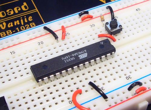
ATmega8 (works the same with ATmega168, and 328) straddling the middle row of the breadboard
You will need to slightly bend in the legs of the DIP (dual inline package) to get the ATmega to straddle the breadboard center. Be careful! Do not bend the pins too far inward. The pins of the ATmega should insert into the inner two most rows on the breadboard. I find it best to to insert one side and then slightly push the IC sideways until the other side of pins can insert into the opposite row on the breadboard. Confusing, I know.
Note: The 5V 'rail' is the horizontal row of holes next to the red line. You should have a wire connecting your 5V power regulator circuit to one hole on the 5V rail. This will energize all the holes next to the red line with 5V. This is true about the blue line as well. All the horizontal holes next to the blue line are connected together. One of these holes should be connected to the ground pin on your voltage regulator, and to the ground connection of your wall wart. You can connect the VCC pins on the ATmega328 to any holes along the 5V rail, and you connect the GND pins on the ATmega328 to any hole along the blue GND rail.
Oh, hey! If no one ever told you, there is a really simple way to figure out where pin 1 is on an IC. The manufacturer of anything polarized (tantalum caps, electrolytic caps, LEDs, ICs, etc) will always put some sort of marking on the device to indicate the how the device is supposed to be oriented. For ICs, there is a small dimple on one end of the IC. The blue arrow in the picture is pointing to this dimple. The orange arrow points at pin 1, and the blue labels show how the pin numbers increase.
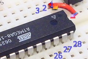
Pin labeling on an IC
Counting from the dimple, pin 1 is on the left and increases down the left side of the IC. The pin numbers jump to the right side row of pins and count up. See image from the ATmega328 datasheet below.
The ATmega328 should be in the breadboard, pin 7 (VCC) and pin 20 (AVCC) should be connected to your 5V rail and pins 8 and 22 (GND) should be connected to GND on your bread board. If you turn your power circuit on, the ATmega328 is now running, but it has nothing to run!
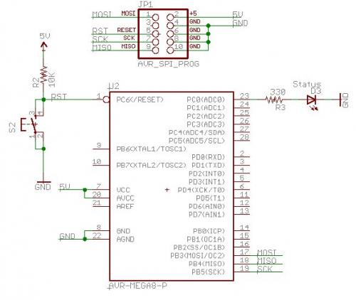
Actually this is not wholly true - there is one more connection that needs to be made before the ATmega328 starts running code. The RESET pin on the ATmega328 needs to be connected to VCC. You can either wire the RESET pin directly to 5V or you can 'tie it high' by connecting the RESET pin to VCC through a resistor. This will allow you to add a momentary reset button. What's this? The reset line on the ATmega328 is exactly what it sounds like - it resets the micro just like the reset works on your computer. If you look at the ATmega328 datasheet you'll see the RESET label is written with a line above it. This is nomenclature that indicates the reset pin is active low. What is 'active low'? The RESET pin is an input. A low level on this pin will put the micro into reset - i.e. the pin is activated with a low input, aka 'active low'. So unless you want your ATmega328 to stay in reset, you'll need to pull this pin high.
Now you need a reset button. A momentary switch is a switch that is activated (or closed) while you're touching it and open when you release the button. These are often called 'tactile switches' because they 'click' when you depress them giving the person pressing the button some 'tactile' feedback.
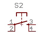
This is what the schematic part looks like. Notice pins 1 and 2 are connected together. 3 and 4 are connected together. And when you press 'de button, it temporarily connects 1/2+3/4 together.
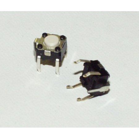
Notice this button has five legs. If your button has five legs, just ignore the middle leg - it's not connected to anything and can be clipped off.
To test this button, whip out the trusty multimeter and set it to the continuity setting. This is the setting on nicer, mid-grade multimeters that is crucial to troubleshooting and experimenting. Touch the probes together - you should hear a tone indicating that there is continuity or a (nearly) zero resistance path between the probes. Insert the button into the breadboard and probe the two pins on one side of the button. If you picked pins 1/2 or 3/4 you should hear a tone. These pins are permanently connected inside switch. If you picked pins 1/3 or 2/4, you won't hear a noise - but hit the button. By hitting the button you will make an electrical connection between all four pins - and you should hear the tone! This means you have electrical continuity.
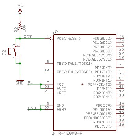
The schematic shows pins 1 and 2 of the reset switch connected together (connected to ground) and pins 3/4 connected together (connected to !RESET) . In practice, you just need the switch to work. Play with your multimeter and find two pins that don't make noise when the button is not touched, and do make noise when the button is depressed. Use these two pins.
The schematic shown above is what we're going for. The 10K resistor 'pulls' the reset pin high during normal activity. By pulling the reset pin high, the ATmega328 runs normally. When you push the reset switch (S2), the reset pin sees a continuous connection to ground. Since the resistance through the depressed switch is nearly zero, it wins (compared to the resistance of the 10K resistor!) and the reset pin is pulled low, RESET is activated and the ATmega328 goes into reset. Release the button and the reset pin is pulled high again and the ATmega328 comes out of reset. Nifty!
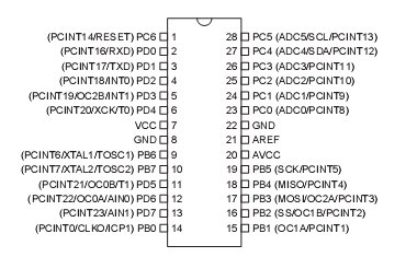
ATmega328 pinout
See the dimple from the ATmega328 datasheet? Looking at the top of the IC (legs down), with the dimple to the top, pin numbers increase starting from 1 in the top left corner. This is how every IC pin is numbered. However, the orientation marking varies a bit between manufacturers and between packaging types. Look for a non-congruent marking like a dimple, small dot, white arrow, a notched corner - anything that makes that area of the chip different from the other parts of the chip probably indicates pin 1. When in doubt, check the datasheet.
Reset wired next to a ATmega8 (same applies for the ATmega168, and ATmega328)
Learn how to use the the continuity setting on your multimeter. It will be vital to troubleshooting down the road!
Each microcontroller manufacturer has a different method to get code in the flash memory of the micro. In the past few years there has been emphasis placed on ISP or "in system programming". ISP allows you to program the IC without having to disconnect the microcontroller from the application. This is not trivial! History was much more painful. Atmel has designed a relatively straight forward method that requires the control of a few pins (6 total). Because of this simple interface, the hardware programmer that is required to connect your computer to this ISP interface is very straight forward (cheap!) as well.
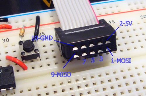
The red stripe indicates the location of Pin 1
Remember how we identified pin1 on the IC from the dimple? Well connectors also need polarization so that we don't reverse the orientation of the connector and fry things. Unfortunately the way connectors are numbered is opposite that of ICs. In the picture of the ISP connector, you see the red stripe indicating pin 1. An IC counts sequentially down one side. Connectors on the other hand, increase pin numbers, back and forth, as you work your way down the connector.
The programming chain looks something like this:
-
There is a free C compiler called AVR-GCC. User writes code in C and then compiles that code into HEX files
-
AVR-GCC can be installed on the Windows platform with an easy WinAVR install program
-
The user gets this HEX code onto an AVR via the ISP pins
-
Both a serial port programmer and a parallel port programmere have been designed to connect the computer port to the AVR ISP pins
-
The computer runs a command line program to transfer the HEX file from the computer, to the serial or parallel port, and out to the AVR ISP pins
-
The micro runs the machine code (*.HEX files) once powered or reset
What's a C compiler? This is a program that inputs a program written in the C language and outputs a HEX file. We prefer to program in C because it is easier for us than assembly and more flexible than BASIC.
What's a HEX file? This is a file that contains various hexidecimal characters. These hex 'codes' represent machine instructions that the ATmega328 understand. This file is what gets sent down to the programmer, and the programmer loads these machine instructions onto the ATmega328.
Before we can get too crazy, download and install WinAVR on the computer that you will be doing your code development on. If this link goes out of date, a google search should take you straight to it. The windows install should be fairly straight forward - follow all the defaults. WinAVR contains a version of the GCC compiler and various other tools including avrdude and Programmer's Notepad. avrdude is a simple command line program that takes a HEX file and sends it to the serial or parallel port for programming onto an Atmel microcontroller.
Working backwards up this list, I'll provide you with an example 'Hello World' HEX file that will prove that everything is working correctly on your micro. With any micro controller board, the first trick is always to get an LED to blink. This is the 'Hello World' of embedded systems. Guess what blink_1MHz.hex does?
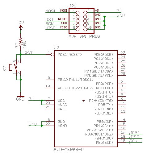
With the blink hex file in hand, you now need to get it onto the micro. You will need to connect the AVR-PG1 (or the AVR-PG2) to the ATmega328. The easiest way to do this is with 9 wires running from your breadboard to the 10-pin connector on the ISP connector on the AVR-PG1/PG2.
Jamming wires into the ISP connector is not a good long-term solution but for the sake of getting the LED to blink, it'll do. I've cut short wires and stripped both ends. One stripped end is inserted into the end of the black programming connector, the other end is inserted into the breadboard.
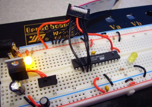
The AVR-PG2 parallel programmer wired into the ATmega328. I've also wired up two 0.1uF caps. These decoupling caps are placed near the VCC and GND pins on the ATmega328 to help reduce noise into the IC. You may think you have a straight DC 5V but not really - these 0.1uF caps help reduce ripple on the 5V line. Yes, the ATmega328 will probably run without them but they're good to have installed.
AVR ISP Note: You really do have to wire all 4 GND pins. You cannot wire just one of the GND pins on the ISP connector.
Additionally we need an LED to control. This can be tied to any GPIO pin. PC0 looks like a good spot.
The resistor/LED order does not matter - just remember (from Tutorial 1) that you must have the resistor! The GPIO pin doesn't actually matter. blink_1MHz.hex will toggle all the pins on all ports so you can hook the resistor to any pin. As you add more peripheral hardware you will want to dedicate some pins for alternate use (such as TX and RX pins for serial communication).
You're getting closer! Time to program the chip!
Once WinAVR is installed, you should have a few new icons on your desktop. Programmers Notepad is a nice code editor and highlighter.
What's a code editor/highlighter? When programming, you will need a text editor on your computer so that you can create (type) code. Once you've created this 'code' on your computer (inside the code editor) you will pass this code to the compiler (you will click a button that runs the compiler with the C file you've typed) and the compiler will create a HEX file (assuming there are no problems or typos in your code). The highlighter? When creating code, it's often nice to have various parts of your program color coded so that you can tell a common things like for( ) and #define. This highlighting helps a lot when programming.
Use whichever text tool you like. Notepad will work, but is pretty rudimentary. I also like JFE from my PIC days. Both have a 'tools' option which is great but JFE is better in my opinion because it lists the C functions that you can double click on and navigate to. If there is a way to do a similar trick in Programmer's Notepad 2, please let me know! Because Programmers Notepad v2 (aka PN2) comes with the WinAVR installation, we'll use it!
AVR-GCC is extremely powerful, very complex, and difficult to use initially. I am used to passing a *.c file to a PIC compiler (CC5x) and getting a HEX file back out. No fuss, no mess. Believe you me, the pain of getting AVR-GCC up and running is worth it. AVR-GCC is a truly nice compiler, and it's free. I've included a stock Makefile and blink_1MHz.c file in blink_1MHz.zip to get you started. I am by no means a Linux or make type of person. All you need to know is that when you type 'make' at the command prompt, the compiler is going to look for a file called 'Makefile' (no file extension!) and use that file to direct how to compile your C file.
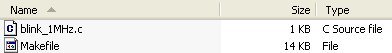
These are the only two files you should need to get blink to compile. Open up blink_1MHz.c in programmer's notepad and click on Tools->Make All. This is the same as typing 'make all' from the command prompt from what ever directory you saved these two files. For example
C:\Code\Blink>make all
should compile your code as well. It's just a bit easier to do this through the Programmer's Notepad interface rather than toggling back and forth to the Command Prompt window. Once you have successfully compiled the C file into a HEX file, you now need to get that hex file onto the AVR. It's finally time to power up your system! The cheap AVR programmers require the target (that's your breadboard) to provide power to the programmer (that's the AVR-PG1 or PG2). Power up your bread board - you should see the power LED come on. From here on out, I will assume you're using the AVR-PG2 parallel port programmer.
There is only two spots in the makefile that you should be concerned about at this time. These two spots are located under the programming options section. This makefile is huge, but scroll down to the Programming Options (avrdude) section. Now put a '#' in front of lines you want to comment out.
If you're using the AVR-PG1 (serial port programmer) you edit like this:
#AVRDUDE_PROGRAMMER = stk200
AVRDUDE_PROGRAMMER = ponyser
# com1 = serial port. Use lpt1 to connect to parallel port.
#AVRDUDE_PORT = lpt1
AVRDUDE_PORT = COM1
If you're using the AVR-PG2 (parallel port programmer) you edit like this:
AVRDUDE_PROGRAMMER = stk200
#AVRDUDE_PROGRAMMER = ponyser
# com1 = serial port. Use lpt1 to connect to parallel port.
AVRDUDE_PORT = lpt1
#AVRDUDE_PORT = COM1
Of course the port numbers depend on your specific computer but once you get things working, you'll be set for life. Assuming you've edited and saved your makefile, go back to PN2. With your breadboard powered, click Tools->Program. This will send the command 'make program' to the command prompt. If everything is setup correctly, you should have successfully loaded blink_1MHz.hex onto your target ATmega328 and your LED should be blinking.
If you get an error :
can't open device "giveio"
Then read this page. Basically you need to copy the giveio.sys file from C:\WinAVR/bin to the C:\Windows directory, then type install_giveio.bat at the command prompt.
Typical Problems:
If you still are not able to program the AVR - this is where 99% of first time users end up. Dig in and troubleshoot.
Are the ISP connections correct? It's easy to get the ISP connector backwards. Take a look at the photos above.
Is there a loose wire? Pull out the multimeter and check that you've got 5V being delivered to the VCC and GND pins on the ATmega328. Do the wires going into the ISP connector have a good solid connection?
Do you have your ATmega328 connected to both power and ground?
Is your 5V supply outputting 5V?
Do you have the right COM port or LPT port selected in your makefile?
There is a multitude of things to check. It's hard! I know. But once you get things correctly set up, and that LED blinks - it will feel fantastic!
Ok - I'm going to assume that you got the code correctly loaded onto the AVR and that the LED is blinking. Congratulations! You are now well on your way to a whole world of pain! Once you get one thing working, it's hard to stop! GPS, datalogging, RF, PCB layout - it's all just a couple hops away.
You can get all the parts for this lecture here.
Here are some additional resources for AVR programming:
-
http://www.salvitti.it/geo/sequencer/dev_tools/tutorial/GNU_C_Tutorial.html
- http://palmavr.sourceforge.net/cgi-bin/fc.cgi
We love feedback! Please report typos, comments, or recommendations to spark@sparkfun.com.
Lecture 1 - Background and Power Supply
Lecture 2 - How to Get Code Onto a Microcontroller
Lecture 3 - What is an oscillator?
Lecture 4 - UART and Serial Communication
Lecture 5 - AVR GCC Compiling
Lecture 6 - Soldering Basics
Lecture 7 - SMD Soldering
Lecture 8 - Eagle: Schematics
Lecture 9 - Eagle: PCB Layout
Lecture 10 - Eagle: Creating a new part
Common Mistakes, Tips and Tricks
-------------------- Tech Support Tips/Troubleshooting/Common Issues --------------------
Hardware Setup
The Pocket AVR Programmer can be used with this tutorial "Lecture 2 - How to Get Code Onto a Microcontroller" https://www.sparkfun.com/tutorials/93. This tutorial was originally referring to two other programmers and not the AVR Pocket programmer. The circuit had to be modified a little to get it working. First, you need to build the circuit on the breadboard. I didn't need to add the voltage regulator to my setup since the AVR Pocket Programmer can provide the 5V. Make sure that you flip the switch to "Power Target." I did use two 0.1uF decoupling capacitors in the circuit, LED for blink, LED for power, reset button, and associated resistors as explained in the tutorial. One thing I did was to add a 16MHz crystal on pins 9 and 10 of the Atmega328p.
Install Driver and WinAVR
Make sure that you install the driver for your Pocket AVR Programmer. They can be found in the documents section under the Windows Driver link. After installing, the Pocket AVR Programmer will come up as a new tree under libusb-win32devices -> USBtiny.
Also, make sure that you are installing the latest version of WinAVR http://sourceforge.net/projects/winavr/files/. For more information on Downloading, Installing, and Configuring WinAVR, check out this pdf => http://winavr.sourceforge.net/install_config_WinAVR.pdf.
Modifying the Make File
I had to do some modifications in order to use the Pocket AVR Programmer in the old tutorial. I was using the ConText editor [http://www.contexteditor.org/index.php] instead of Programmer's Notepad or JFE that was explained in the tutorial to modify the Make File. The code in the ConText editor was highlighted using the C/C++ option to read the file easier. Under the section that says "Programming Options (avrdude)," I had to modify two lines to get the Pocket AVR programmer working:
1.) In line 200, change:
AVRDUDE-Programmer = stk200 to AVRDUDE-Programmer = usbtiny
2.) In line 207, change:
AVRDUDE_WRITE_FLASH = -U flash:w:$(TARGET).hex to AVRDUDE_WRITE_FLASH = -F -U flash:w:$(TARGET).hex.
The first modification was to set the programmer to use the Pocket AVR Programmer. The second line is to override a certain check by avrdude. I found this in the comments but didn't run into this issue before and after modifying line 207. Keep in mind that # comments out a line.
Compiling Hex File
Open up the Command Prompt. I placed the blink_1MHz on my desktop but you can place it anywhere in your computer. Just make sure that you are in the same directory in the Command Prompt. Make sure that you know how to navigate through folders => http://www.wikihow.com/Change-Directories-in-Command-Prompt. After entering the correct directory, type make all to compile the hex file. This will output a lot of files in the blink_1MHz folder. The most important is the .hex file.
If you want to change the c file, you must modify the c file, type make clean in the command prompt, and type make all again.
Setting Fuse Bits, Uploading Hex File, and Setting Lock Bit
You should try looking at the tutorial for installing an Arduino bootloader => https://learn.sparkfun.com/tutorials/installing-an-arduino-bootloader/selecting-a-programmer. This will help in getting the correct connections from the programming cable to your breadboard Arduino. I double checked with a multimeter to check the wiring under the continuity setting. Also, the section under "Uploading Code - Hard Way" will be useful when in the Command Prompt to set the fuse bits, upload the hex file, and set the lock bits. The syntax is sensitive and you can have problems if you don't write the correct commands.
Since you are in the same directory already from compiling the hex file in the Command Prompt, you just need to type the two lines as stated in the tutorial to set the fuse bits and then upload the hex file and set the lock bit. Make sure that you change the hex file in the line ...flash:w:hexfilename.hex... to ...flash:w:blink_1MHz.hex...
For more information, I recommend checking out the avrdude manual on the other options => http://www.nongnu.org/avrdude/user-manual/avrdude.html#Top.
After doing all this setup, I was able to get the Atmega 328P microcontroller to blink with the Pocket AVR Programmer. Hope this helps.
For an Arduino Bootloader, check here => http://code.google.com/p/optiboot/. This uploads the Arduino Uno Bootloader so that after using the programmer for the first time, you can upload firmware with an FTDI and the Arduino IDE without the need of the programmer.
I just got this working, programming with winAVR on winxp. I'm using sparkfun avr programmer to program the chip. Here's what I had to do: download & install winavr download and install the usbtinyisp driver from adafruit.com in the makefile:
AVRDUDE_PROGRAMMER = stk500v2 # not sure if this is really necessary
append '-F' (without quotes, of course) to AVRDUDE_WRITE_FLASH (this is due to avrdude not recognizing the atmega328)
AVRDUDE_PORT = # yes, that's right, no port, COM, LPT, or otherwise. usbtinyisp uses a protocol all its own. why, I ask?
With that, everything is just peachy -- the lil' led blinks as expected. Next is to get this going under linux...
Oh and it also works if I hold down the reset button while I run avrdude.
on ubuntu hardy avrdude wouldn't program the micro and gave the following message:
avrdude: Yikes! Invalid device signature.
avrdude: Expected signature for ATMEGA168 is 1E 94 06
After I connected pin1 on the micro to the programmers RESET or SS pin avrdued was able to program it and the light blinks.
Why doesn't this tutorial say anything about connecting SS to pin1?
A superbly written article
Hello, and thanks for these tutorials. I finished this fun project and enjoyed watching the LED blink. So I started poking around in the C file and found the timing where the 3 pins are on for 500 ms and off 500 ms. So I started changing these numbers, on 800 ms, off 200, then on 200 ms and off 800. Once I realized how to use PN, this worked fine. The steps are to save all, then Make Clean, Make All, and Program. This works great. But now I have encountered a behavior of the chip that I am curious about. When the parallel connector is plugged in to both the computer and the board, the LED blinks like it is supposed to, 500 ms on and 500 ms off. BUT, when I unplug the connector from the computer, it seems to revert back to one of the programs I was playing with, and the LED blinks at approx. 200 ms on and 800 ms off. So, it seems there are two programs that will run, one when the board is connected to the computer and one when it is not. I assume the 200/800 program is the one stored on the chip and the 500/500 program is stored either also on the chip or somewhere else, such as in the computer? I don't understand this. Is the problem that I haven't completely erased the old program from the chip? Is there a method for doing that? Thanks.
blink blink blink oh such a pretty sight after hours of troubleshooting ;)
I did this with an atmega644 and it programmed fine but the LED wasn't flashing - turns out my problem was I had the LED the wrong way around, negative to PB0 (or various other pins), positive to 5V through a resistor. Why is this? Do the pins on 644s work in a different manner .. ?
None of the pictures are showing up for me anyone else?
Same here. Please fix this!
Me too. Graphics are missing from this turorial: Beginning Embedded Electronics - 2
Please help. I am trying to run the blink but keep getting this error:
"can't open device "COM1""
what should I do, any help?
-------- copy from the program-----------
avrdude: serbb_setpin(): SetCommState() failed: The handle is invalid.
make.exe: *** [program] Error 1
Double check that your COM ports are correct. It may not be COM1 on your machine.
I can't get the pocket programmer to recognize the chip. It works on an Arduino, so I know the computer setup and the pocket programmer are OK. I have verified 5v and gnd to the correct pins. I discovered an error in my reset pin connection. I had the 10K resistor connected to gnd instead of 5v. Could that have fried the chip? If not, what else can I check?
Hi i don't have 330 Ohm Resistors i only have 360 Ohm Resistors can i use them i also have 220 Ohm Resistors ?
If you're running Windows 7 and getting "Access is denied." when trying to install_giveio.bat, try right clicking the command prompt and running as admin. Good catch J.R.!
For the rank noob's like me.
some issues that arent explained real well for the pocket programer and programmers notebook.
The uncompressed blink file and make file must be in the same folder, (windows 7 would not prperly uncompress the saved files until i moved them, even though you can view them they were not uncompressed as far as programmers notebook was concearned.
a quick note on using programmers notebook,
upper and lower case is important!!!
in "tools" use make clean to clear out the previous compile in the register (you wont lose the file's_) then make all to compile it, then make program to write the program to the chip.
The standard make file has problems with the pocket programmer. make the following changes.
MCU = atmega328
AVRDUDE_PROGRAMMER = usbtiny
AVRDUDE_PORT = usb (this one is probably not necessary)
AVRDUDE_FLAGS = -p $(MCU) -P $(AVRDUDE_PORT) -c $(AVRDUDE_PROGRAMMER)
AVRDUDE_FLAGS = -c $(AVRDUDE_PROGRAMMER) -p m328p
once I made these changes it woked fine, I left the -b off due to comments on AVRDUDE's site.
Good luck.
I am having a lot of difficulty getting the chip and the switch to lock into the board. I seems the board is to deep or the pins or to short on both, can not push either in far enough, they are just sitting on top with no solid connection. Has anyone else had this problem? Do I have a defective board?? removed backing and "fingers" are all seated - no help.
Hi!
I am still getting the message "cant open device giveio", I ran install_giveio.bat several times, but to no avail, I always get an error message!
By the by the website you have provided for solving this problem doesn't work anymore!
For those having trouble with "giveio" in Windows 7, see this website.
http://www.avrfreaks.net/index.php?name=PNphpBB2&file=viewtopic&t=88034
Basically it says, copy the 'giveio.sys' to 'c:/windows/system32', and then run 'install_giveio.bat' as an administrator. (run as admin: right click on command prompt and click run as admin)
Thanks J.R., I've been working on getting install_giveio.bat to run for hours! Right-clicking and running as admin on Windows 7 did the trick. You're a life saver.
Woot Woot, glad I could help!
How do we do this with USB? Please HELP!!!
AAARRRRHHHH! How do I use the Pocket AVR Programmer with this?!?!?!
I don't know how to do this through WinAVR but you can program the micro using AVRDUDE using the command prompt. First copy the hex file to c:\ and then run this from the command prompt: avrdude -c usbtiny -p m328 -U flash:w:blink_1MHz.hex. Just replace m328 with your particular micro type.
Windows 7<br />
Install WINAVR<br />
Look at your PATH variable<br />
I spent hours trying to figure out why I couldn't ping a network address from the command line, when I finally decided to look at my PATH variable. What was there?
C:\WinAVR-20100110\bin;C:\WinAVR-20100110\utils\bin
The installer seems to have removed every other part of my PATH variable.
I would recommend making a copy of your PATH before installing WINAVR.
Good tutorial! I finally got the ATmega328 working with this program before moving onto the next tutorial where I fried it. But, got it all working on a new chip.
Hope the PATH advice helps.
I bought the kit for the tutorial and made it painlessly up to the point of programming the 328. No blinky, inconsistent messages (which should have been a clue itself), and a bad link for the 'read this page' for the giveio problem. Frustration starts here. Granted, this is a basic embedded tutorial, but a little more detail beyond some trial suggestions for the 'What now, when things don't work?' would be nice, so here's some:<br />
<br />
First, I did some web surfing. (Actually, first, I copied the giveio thing and installed it, but I don't know if that had any signficant impact on my results or not.) The ATmega328P is programmed using an SPI (Serial Peripheral Interface) connection. This is well-documented in ATMEL application (app) note 910(http://www.atmel.com/dyn/resources/prod_documents/doc0943.pdf). From that, I learned that the information flowing from the laptop to the 328 is mostly controlled by SCK (pin 7 on the ICSP connector of the Olimex (AVR-PG2/STK) programmer) and MOSI (pin 1), so I started there. The guts of the Olimex connector are shown in: <br />
http://www.olimex.com/dev/pdf/avr-pg2b.pdf. Extra points for getting the data sheet on the 74HC244 inside it. I <br />
worked backwards through the 74HC244, and saw that SCK is driven from DB-25 pin 6 and MOSI from pin 7. I've got an oscilloscope, so I probed these two pins looking for signs of life, pulling my ground reference from pins 18-21 (I used 19, IIRC). No joy when I hit 'Program' from Programmer's Notepad. LPT1 wasn't playing. If I didn't have the o-scope, I'd have hooked up my trusty voltmeter (or a pulse catcher, if I had one). I ran across some programs on the web that turn the parallel pins on or off for debugging, so these could be used to see if your PC actually drives the parallel port from LPT1. They'd be handy with the voltmeter, but with the oscilloscope I didn't need them. Per some of the other commenters' suggestions, I tried lpt2 and lpt3, but still got nothing. I don't have a lot of patience for trial-and-error debugging anyway.<br />
<br />
I got WinAVR loaded onto my Gateway laptop, model M685-E, running Windows XP (Service pack 3), and using the parallel port on its docking station. The BIOS setting (F2 on power-up) for my parallel port was set to AUTO. I'm not quite sure what AUTO means, but given the choices of AUTO, ENABLE, or DISABLE, I changed it to enable. I was also given four choices for MODE. Given that I needed to hear back from the 328 on MISO, I didn't even bother trying 'output-only'. 'Bi-directional' didn't result in any output either, but I got wiggles using LPT1 for both 'EPP' and 'ECP'. The BIOS addresses were both 378 and I didn't feel the need to change them. Further creative scoping showed the wiggles included the $AC53 string used to put the 328 into programming mode, so my port problems were apparently fixed. Next, it was time to hook the hardware back up.<br />
<br />
Per the app note, the 328 is designed to set all its port pins as inputs while it's in reset mode, readying it to receive programming commands. Note that reset means pin 1 is grounded (Can we get the Sparkfun folks to correct the chip pinout picture in this tutorial so RESET has a line over it, please?). For those looking at the Olimex schematic, pin 5 does not appear connected at first glance. But if you look at IC1B, outputs Y2,Y3, and Y4 are wired to a little diamond/circle doodle with '(5)' above it. This notation is used sometimes in schematics to denote a connection when drawing a wire might make the schematic harder to read. For the unwitting, it ticks another point on the frustrate-o-meter. So according to this, the 328 reset is driven from DB-25 pin 9. All goodness so far.<br />
<br />
While we're looking at this schematic, also note ICSP pins 4,8, and 10 aren't connected to anything. In fact, the wires are physically cut off inside the Olimex programmer (The one I just got, anyhow). Despite the bold note in the tutorial about the ground pins, it just ain't true (or at least it isn't for me). Pin 6 is the only one that counts. So ultimately, you need six wires, not nine.<br />
<br />
Looking further at the Olimex schematic, notice that the power for the IC comes from the ICSP connector (through a diode). This makes it possible for the IC to operate at (and output) a different voltage than the parallel port that's driving it. This is NOT trivial.<br />
<br />
The wiggles from my parallel port were around 3 volts. I guess I shouldn't be surprised; manufacturers of systems with parallel and serial ports (especially laptops) have notoriously played fast and loose with port signal voltages for years, and you can't count on them.<br />
<br />
I was operating the 328 (and ICSP pin 2) at 5 volts. There was a .25-volt drop across the diode, so the 74HC244 was operating at 4.75 volts, which was still significantly higher than its 3-volt inputs. Chips like this have a defined minimum input voltage before they recognize the input as a logic '1' (It's on the datasheet). The higher the operating voltage, the higher the minimum input '1' voltage. Below this voltage, all bets are off, which I think contributed to my inconsistent initial results.<br />
<br />
I have a dc supply, so I skipped lecture 1. The 328 is designed to operate at voltages down to 1.8 volts, so I simply turned my supply voltage down (4.3 volts, in my case), to get the 74HC244 operating voltage more in-line with its inputs. Blinky blinky. Smile. Obviously, you folks with the 7805's can't simply turn down your voltage like I did (if that's truly your problem). There are ways to bias the 7805 to get something other than 5 volts from it, but the LM317 is better suited to being used in a variable supply. If you check out the schematic for this kit, you'll see it's set up roughly the same as your 7805, but instead of grounding it directly, there's some resistors there to control it (some folks use a trim pot): http://www.sparkfun.com/products/114<br />
<br />
Last note to all you who have been fortunate enough to be mesmerized by your new blinky: I turned off the laptop and the blinky stopped blinkying. I'd left the programmer attached, so turning off the computer also turns off the parallel port (duh). Seeing zeros on the parallel port forces the programmer to hold the 328 in reset mode, preventing it from running. If you yank the reset line from the programmer to port 1 on the 328, it blinkys again. <br />
I'm waiting on my parts to start this tutorial so I cant test the voltages, but I'm confused on the RESET section. If there's a 10k Resistor between the 5V supply and Reset pin, wont the Reset pin see a significantly lower voltage than 5V? I'm new to all this, just trying to understand. Thanks!
Does the reset pin just care if there's some voltage there? So it doesnt reset if it see's some voltage, but when the reset button is pushed, the voltage drops to zero on the reset pin, because there's a clear path to ground?
Yeah guys, the reset pin is active low. So in the digital world, for all intents and purposes high is anything just below 5v (or 3.3v if you're running a 3.3 system) and low is anything just above 0v. Where they meet? That varies from chip to chip (there's a tut on it in the new bite-sized primers section) You seem to understand pretty well whats going on: The pin sees about 4-5v so it's "ON" but when you push the button it grounds the incoming voltage and the pin gets about 'nothing' volts. <br />
What you're doing though is forgetting that the point of the switch ISN'T to route the RST pin to GND, it's to route the voltage off of the resistor to GND (Before it can reach the pin to pull it up) So when you push the switch you're sinking not only the chip to GND but also the system voltage, and what do you get when you ground the system voltage without a resistance? That's right: a short! So the resistor is there so that when you reset the IC, it doesn't short your supply. Sure, the IC would reset without it, but things might spark when you pushed the button, lol.<br />
<br />
Cheers!
It took me four hours but finally got this going. I originally tried on my LPTless laptop using a USB to parallel port dongle through a virtual machine (long story) but could not get it to work. I then added a PCI parallel port to my desktop figuring that the Programmers Notepad was looking for a specific address and this did not work either with lpt1. I had been over and over the wiring, so I went into device manager (devmgmt.msc at command line) and opened the PCI parallel port device. Under the resources tab it lists the IO location so I specified the starting location ("0xec00") instead of "lpt1" as the value for AVRDUDE_PORT in the make file. I also changed the MCU value to "m328p" to match my chip as suggested in other posts. Have to remember this is all case sensitive. Finally works. Hopefully this will help someone else now that parallel ports are hard to come by on modern machines.
These tutorials are great, thanks for making them (I bought the kits for the first few from Sparkfun)
My blinking LED worked first time :D There is one step missing from the tutorial - the first line of the makefile needs to be altered - change MCU name to match the micro you have.
MCU = m328p
worked for me with the micro provided in the kit. (Run make all and program after this change)
I would also like more explanation about the "decoupling" caps added in the photo that are not shown in the schematic - or even a link or search term so I could learn the purpose of these caps.
If you have 5v before the 10k resistor at the reset switch, but 0v after the resistor is it fair to say there's a short in the circuit on your breadboard someplace? I have a two 8 bit shift registers hooked up to the avr and a bunch of leds hooked up to the shift registers.
Note that when the programmer is hooked up and supplying power to the avr, it runs, but when it's not hooked up, the reset line goes low after the resistor, but not before but the end result is that avr is in reset.
I initially hooked up the pins on the connector in reverse. If you look at the schematic and then look at the picture of the connector with the blue text pointing out the pin locations the schematic is the reverse of the picture if you are holding the connector in your hand with the red strip oriented up.
At any rate, if I hook it up as in the picture, not as in the schematic, I get 0v on the reset pin into the atmega328. If I remove the reset pin wire from the connector I get 5v going into the reset pin on the atmega328.
Did I fry the pocket programmer? Would it really be that easy to fry?
So I can't program the mcu because it's being held in reset. Any reason why the connector connections would pull that line low? I know, a short to ground, but this is a brand new unit received in the mail from sparkfun a couple days ago.
After probing the connector pins to figure out exactly where 5v was and then reconnecting all the wires, I was able to program the atmega328 with
avrdude -p m328p -c usbtiny -U flash:w:blink.hex
I am stuck trying to use avrdude from the command prompt to 'check in' with the atmega 328 (or is this the Atmega328P? It says P on the chip but not on the sparkfun product page) Whichever one it is, the DIP is on the breadboard and wired for power and wired to the 6 pin programming header via USBtinyISP. Everything seems to be in place exactly perfectly, avrdude says 'hello' to the USBtinyISP but not to the chip. What is the exact command line to get avrdude to 'register' with the chip?
For development on Mac OS X, you can download CrossPack for AVR instead of WinAVR. It can be found at http://www.obdev.at/products/crosspack/index.html
The Piconomic FWLIB has been revised and updated. The following link is old:
http://piconomic.berlios.de/avr_quick_start_guide.html
It is now hosted at:
http://piconomic.co.za/fwlib/_a_v_r___q_u_i_c_k___s_t_a_r_t___g_u_i_d_e.html
Enjoy!
Pieter
Great tutorials, and dito comments. They've made me able to let the LED blink, via USB and @ 16 MHz. As a next experiment I've recently tried to programmed another simple thing (I try to activate one pin via a switch, once activated another pin needs to burn a LED for a couple seconds).
So I've edited the Blink_1Mhz file and saved it as Tijdschakelaar. Then "Saved as" the makefile you've supplied in the same folder and edited it (actually just changed Target = Blink_1Mhz to Target Tijdschakelaar). Thinking this would do all I got was: Did not find rule to make Tijdschakelaar.elf.
What could be the problem? Probably something dead obvious.
Greetz from Belgium.
my laptop doesnt have a printer port. how do i use usb to program?
Is there any way to get the computers serial port to program the atmega328 via a .hex file?
Just a question; how would you program the ATmega if you don't have a parallel (printer) port on either your desktop or laptop?
If you're using the USBtiny pocket programmer for the tutorial, do not include the -B 1 command line prompt at this stage: the microcontroller's not fast enough to keep up with the programmer using the -B 1 switch.
In the makefile, I have these settings:
MCU name
MCU = m328p
Programming hardware: alf avr910 avrisp bascom bsd
dt006 pavr picoweb pony-stk200 sp12 stk200 stk500
AVRDUDE_PROGRAMMER = usbtiny
com1 = serial port. Use lpt1 to connect to parallel port.
AVRDUDE_PORT = COM6
(I'm not sure avrdude looks at the com port for a the USBtiny programmer.)
Also, wiring up the 10 pin connector is kind of a bear. I used the 6 pin instead. Note that the connector is keyed. If you hold the connector so the holes are facing you, here are the pin numbers:
6 4 2
5 3 1
where the key protrusion is on the bottom, below pin 3. The pins are as follows:
1 - MISO
2 - VCC (+5 volts)
3 - SCK
4 - MOSI
5 - RST
6 - GND
thanks's so much! Without this post I never would have gotten my first led blinking.
Will this work with a home made DAPA parallel port programmer as described in this link: http://www.arduino.cc/en/Hacking/ParallelProgrammer
I can verify that the parallel port programmer works. Tips on building it yourself. The cable should not be too long and I had to remove the resistor at pin 11 of the DB25 connector. I downloaded the ISP programmer windows software to test it out. If you are using avrdude, the following command should work:
avrdude -p atmega8 -P lpt1 -c dapa
This tells avrdude to identify your device. By default, a virgin atmega8 should have its fuse bits set to run at 1Mhz. You could try adding the 16 Mhz crystals and .22 caps as well if things don't work.
I'm trying to program the ATmega328P using this process, and have not had success yet. I had to add a PCI card to get parallel and serial ports, and haven't been able to verify those ports yet. The XP device manager claims the parallel port is functioning and located at lpt3.
I've checked voltages and SPI connections at least 4 times, and have tried a few variations of lpt port and MCU name in the makefile, but still am getting the "AVR device not responding" error.
I can't tell if there is any major difference between the ATmega328P and the 168 that is the default in the makefile. Any ideas?
For what it's worth, the I/O range for the parallel port is B8A8-B8AF, I guess not the typical address for an LPT port from reading the other posts.
It turns out that if you dig into the avrdude documentation, the ports lpt1, lpt2, and lpt3 are hard-coded to addresses 0x378, 0x278, and 0x3BC. My PCI parallel port is not at any of those addresses.
The command line interface allows for this case, so change line 204 in the makefile to the address of your port
AVRDUDE_PORT = 0xB8A8
I'm not sure if it makes a difference, but I ended up with line 43 in the makefile as:
MCU = atmega328p
instead of 168
Hopefully this helps those who follow after.
What if my PC haven't paralel port ? Can this work for my and how?
gvozdan@gmail.com
I've got it so close I can almost taste (okay, see) the LED blinking, but it comes out with:
avrdude: Device signature = 0x1e950f
avrdude: Expected signature for ATMEGA168 is 1E 94 06
Double check chip, or use -F to override this
check
I'm using a 328 instead of the 168. Does anyone know how to either modify the code so it looks for the 328's signature or use the -F check override? Any help would be much appreciated.
I'm guessing you've got this by now, but I'll leave this note for others. I got the same error.
Open the makefile, and find the line AVRDUDE_WRITE_FLASH. You can append AVRDude command-line options to this line and they will be run automatically when you choose Tools > [WinAVR] Program. Add -F to the end of this line and it will force the write.
As far as I can tell there's no reason you can't use 168 code on a 328 (same chip, more memory) but AVRDude doesn't like it.
Programmed a 328 with the AVR pocket programmer.
Programmed a Tiny13. That pocket programmer is a killer buy, works great.
First off, I too am a rank beginner with the Atmega168, et. al. But I just wanted to share what I might use as a blink.c code to simplify the delay piece:
include
include
// delay.h is a standard avr-libc library module
int main (void)
{
// set PORTC pin 1 (PC0) for output
DDRC = 0x01;
while (1)
{
// set LED off
PORTC = 0xfe;
_delay_ms(250);
// set LED on
PORTC = 0xff;
_delay_ms(250);
}
return 1;
}
Ye gads! I forgot about the stripping of characters here. The include lines should read:
include avr/io.h with 'less than' before and 'greater than' symbols after the avr/io.h. Same with the util/delay.h.
Oops!
I am having trouble loading code onto Atmega168. I am using Serial Programmer. Code compiles fine, but when I go to load code onto AVR, I get the following error:
Two things to check (in case you haven't already).
1. Make sure the power is on (for the AVR)
2. Double check that you're using the right com-port (you're output states 'COM1'). If you're using a USB-to-serial cable, double check which com-port it was assigned in the system-settings.
Hope this helps.
;-> (cjh)
I added a 20Mhz crystal and it worked. When it started it was not running off the 20Mhz crystal, but rather the 1Mhz default...wierd huh?
It now works and I am able to reprogram it now without any problems, and edit the fuse bits to use it at 20Mhz!
Serial com works no problem.
I'm going to buy the kits for lecture 1 and 2, but I have a question. What if my computer doesn't have parallel or serial ports? I'm sure I can get USB adapters, but will they be recognized properly and be able to send it to the micro?
For the most part I got everything working. I was wondering how long it takes to upload a program to your device? I'm using a home-built serial programmer based on the AVR-PG1B schematic. I did have to substitute some of the components and was wondering if that is the root of my slow uploads or if this is just the norm?
;-> (cjh)
Update;
I just pulled out an old laptop that has a com-port and everything works as I would have expected. I guess I'm having issues with my USB-2-serial cable.
;-> (cjh)
These tutorials are great. Thank you very much.
I'm running Windows 7, and when trying to load the code to the microcontroller, I got the following error: can't open device "giveio"
I clicked the link provided in the lesson, but the link was broken. I then used the Windows Explorer GUI to copy C:\WinAVR\bin\giveio.sys to C:\Windows\giveio.sys, went to command prompt, and entered: install_giveio.bat
It outputs the following: Copying the driver to the windows directory target file: C:\Windows\giveio.sys
The system cannot find the file specified.
Remove a running service if needed...
Installing Windows NT/2k/XP driver: giveio
Installing giveio from C:\Windows\giveio.sys... install failed (status 6):
The handle is invalid.
starting giveio... start failed (status 6):
The handle is invalid.
ERROR: Installation of giveio failed
Does anyone have an idea of what I'm doing wrong?
Hi I have a problem. When I download the link for the files, I don't get a makefile, I only get a file alled blink_1MHz. Where did the makefile go to?
I was unable to unzip your blink_1MHz.zip file using WinZip 14. Error states "Cannot open file: it does not appear to be a valid archive."
Does the link in the tutorial still have the blink_1MHz.c and Makefile?
The 10kOhm resistor is in place to limit the current I=(5V/10000Ohm) when the push button is closed. If it were not there the 5V rail would be shorted directly to ground when the push button is closed.
You are GREAT! This tutorial is great too!
Today I made my very first LED blink after 9 hours of constant work and destroying 3 ATMega16 micros! But the last one, by configuring the correct Fuse Bits was correctly programmed!
I am running way beyond this tutorial now, implementing all my simulated Proteus AVR projects in the real world and it is so much fun and amazing!
All work's fine, thank you.
Hello,
Would this all work with ATMEGA8? i'm wondering because it's cheaper and easier to get here, in Lithuania :P
Yes, it will work with the ATMEGA8
OK, I've been trying to figure it out and I can't. Why is there a resistor before the switch connected to RESET? I know it is to "pull RESET high", but how does the resistor do that? Why can't you just replace the resistor with a wire? Thanx!
The resistor is there to limit the current to ground. Otherwise you would be shorting the power supply. Ohm's Law is:
voltage / resistance = current, or:
voltage / current = resistance. So you figure the 10K ohm resistor would limit the current flow through the resistor to 0.5 milliAmps (0.0005 A). This is important as the resistor is most likely a 1/4 watt resistor. The wattage (heating effect) through the resistor is Volts x current = 5 x .0005 = 2.5 milliWatts, much lower than the 250 mW rating of the resistor.
I opened up my stk200 and used the continuity test on my multimeter to make sure the pinouts were right, and I found 3 of the 4 not connected to anything.
Just wondering why all 4 need to be connected when only one is really carrying anything...
Also, the reason I was checking pinouts is that I've now gone through two different ATMega168 chips that don't respond to anything all of a sudden.
Well, the first one did for awhile and then stopped, but it was even buggy then (things like the LED only working until I unplugged the programmer, and then not working until the shield around the pins on the programmer were grounded. Something I found out by accident when I went to plug it back in.).
The second one doesn't work at all. I get zero response.
I thought at first all these problems were due to the fact that I received a 5v wall wart, and with the 5v regular there wasn't enough overhead, so my voltage rail was really around 4.75v. So I just received a 9v wall wart and it's a solid perfect 5v all around now. Still no help, however.
Any thoughts?
Hi!
This link is old:
http://www.piconomic.co.za/avr.php
Please change it to:
http://piconomic.berlios.de/
Best regards,
Pieter
I gad AVR parallel port programer and I fought for hours in order to make blink that damn led. I finaly success in modifing the BIOS parallel port configuration of my computer. Looks like it was realy important for my PC to set it to: ECP (Extended Capabilities Mode) and Port(O/I) 378
Then only lpt3 works, dont ask me why.
I can't get the code to compile for me. I keep getting this error...
Compiling: blink_1MHz.c
avr-gcc -c -mmcu=atmega168 -I. -gdwarf-2 -DF_CPU=8000000UL -Os -funsigned-char -funsigned-bitfields -fpack-struct -fshort-enums -Wall -Wstrict-prototypes -Wa,-adhlns=blink_1MHz.lst -std=gnu99 -MD -MP -MF .dep/blink_1MHz.o.d blink_1MHz.c -o blink_1MHz.o
blink_1MHz.c:60: fatal error: opening dependency file .dep/blink_1MHz.o.d: No such file or directory
compilation terminated.
make.exe: *** [blink_1MHz.o] Error 1
In Windows Vista, I had to manually create the .dep folder in the directory I was trying to compile in. Windows explorer would not let me do this, so I did it through the command prompt.
What was the file you made called? I made one called .depblink_1MHz.o.d and it still doesn't work.
Sorry my backslashes did not show up. I will use arrows to show sub folders instead
C: -> code -> blink_1MHz, I needed an additional folder that I had to manually create 'C: -> code -> blink_1MHz -> .dep'. Once that folder was there, I compiled and it created the .o.d file
I had to make a folder called '.dep' in the directory my .c file was. So if my code sat in C:\code\blink_1MHz\, I needed an additional folder that I had to manually create 'C:\code\blink_1MHz.dep\'. Once that folder was there, I compiled and it created the .o.d file
Sounds like something is going wrong with the Makefile. I'm not all that familiar with Makefiles, but it looks like it can't find a directory/file called .dep/blink_1MHz.o.d -- does the file actually exist (it should be created by the make process itself)?
For those asking about the USBtinyISP, YES, IT DOES WORK! That LED is blinking as I type! :)
I used the 6 pin connector so I could avoid the 4 ground wires. You'll need to reference this schematic on ladyada's site to figure out which pin is which: http://www.ladyada.net/images/usbtinyisp/usbtinyisp2sch.png
The VCC (pin 2) and GND (pin 6) pins are on the same side that as the ribbon. So:
pin 1: MISO
pin 2: VCC
pin 3: SCK
pin 4: MOSI
pin 5: RST
pin 6: GND
It's very easy to get confused at this step -- I had to double-check and rewire many times. Also, make sure you're using the ATmega168 pinout schematic to see where the corresponding chip pins are located -- the schematics for the older chip show the pins in different locations. So, on the ATmega168 chip:
MISO: pin 18
VCC: pins 7
SCK: pin 19
MOSI: pin 17
RST: pin 1
GND: pin 8
You also need to hook up pin 20 to your breadboard VCC and pin 22 to your breadboard GND.
Oh, also, if you're using the USBtinyISP, you need to use the following in your Makefile:
AVRDUDE_PROGRAMMER = usbtiny
Not sure what you'd need to set your port to on a PC, but on a Mac, this works:
AVRDUDE_PORT = usb
I've got usbtiny working on a Windows (Vista) machine, and just like on the Mac, the port should be simply "usb". It's blinking away even as I speak.
In my experience you can leave port = Com1 on a PC as long as you have the USBTiny driver installed and the programmer is = usbtiny<br />
<br />
Also, if you're doing this tutorial with an ATTINY13 just use that as the device name both in the makefile and when you initialize AVRDUDE. The list that avrdude gives you seems to indicate that you should input "t13" but it has no idea what you're talking about if you use that name. Just type "attiny13" <br />
<br />
Furthermore, if you unplug your programmer and find that light stops blinking (even though you're not using the programmer to power the target) yank out the reset wire to the ISP connector. When the power is out on the programmer (at least the usbtiny) it pulls the reset pin low.<br />
<br />
Alrighty, just my little chunk of advice. Have fun!
Before I start these tutorials, showing my ignorance, I need to know what USB programmer works with these tutorials. Does the STK500 work for this in replacement of the AVR-PG2 Programmer or how about the USBtinyISP? It sounds like either would work?
Will the serial programmer(PGM-00014 & CAB-00065) work the same as the parallel one(PGM-00013 & CAB-00064)? The tutorial gives makefile settings for both but the parts package has the parallel port version. Also, is the programmer anything more than wires directly from pin to pin? Can I just connect the wires directly without the programmer?
My other question is about the power supply. Would a 9v battery work better to reduce noise? If it would work, can I just replace the barrel with it and not change anything else? How long would the battery last?
Thank you for your help in advance, I'm new and trying to get started as cheap as I can :)
I followed tutorial 1 and 2 and thought I had it right - but nothing worked. I got an "avrdude: AVR device not responding" message from both, programmer's notebook and the cmd-line. I am using the parallel programmer connected to an IBM Thinkpad.
Eventually I tried an other LPT port - and even though windows makes me believe there is only LPT1 in the system, avrdude works with LPT3 (the LED is now blinking nicely) - but only once.
I cannot reprogram the ATmega unless I reboot my laptop. I get the same error message as before without a reboot.
Does anybody have an idea what's going on? (and maybe more importantly a solution that allows me to reprogram without rebooting)
Thanks in advance.
Would the USBtinyISP usb programmer be a good option to use over the parallel programmer? My laptop does not have a parallel input.
I have the USBtinyISP and it seems to be working great, although I can't get my LED to blink.
Does removing the chip from my programmer and putting in on a breadboard reboot the chip?
After programming i get some errors:
avrdude: verification error, fist mismatch at byte 0x0000
0x0C != 0x00
and
avrdude: safemode: lfuse changed! Was 62, and is now fe
I am also a little confused by the switch.. It doesn't program unless I hold down the reset button. Is that how it is supposed to function?
Would it be possible to get a little explanation of the code. I think I understand all the hardware stuff, but I'm not really sure how the code is working. The only other experience I've had coding micros is with the arduino (language and hardware).
Blinky blinky blinky =D
Apparently it likes the following BIOS settings:
Parallel port address 378
Mode bi-directional
And despite claims that my PC is making about 378 being lpt2, the makefile still wants it to be lpt1.
Next to try to trick it into working with the USB-parallel bridge so I don't have to take the board from table with laptop to P4 box ~_~
Ok I hope this story helps someone... So for the past two weeks I've been trying to get my chips programmed (AVRs & 8052s) but to no avail. It kept saying something about unable to detect microcontroller. I tried four different programmers, home built and store bought, but nothing. Couple nights ago I remembered that when I built my Frankenputer last year I didn't enable the parallel port in the bios thinking "who uses those anymore?" yeah... Opps! But my sever pain in the neck came when I couldn't get back into the bios to turn it on. Why? Still not completely sure but I think it had something to do with me over clocking the thermal snot out of my CPU. So anywho, I had to reset the bios so I could get into the bios, and then turn on the parallel port. All is well now and my blood pressure is back within a healthy range. Moral of the story... Make sure your parallel port is enabled in the bios before the urge to chuck heavy objects at your computer sets in...
HERE IN PICTURE U HAV PUT SOME YELLOW CRYTAL,BUT U HAVNT EXPLINED DUDE
Those are the .1uF supply bypass caps.
wat the reset switch actually does?
can u clearly explain the connections for the ISP?
I don't have a LPT1(DB-25) port or a DB9 port on my new computer. All I have is USB. I opened the tower and I see 1 port unused and it's labeled "USB". The pin diagram is of 9 pins as follows:
[::::']
Is the 9 pin USB connection the same thing as a com port? should I connect the DB25 connector to the 9 pin USB connector?
I couldn't get WinAVR/avr_dude to recognize my ATMEGA168 for the life of me with the parallel port AVR programmer. I bought the AVRISPmkii from DigiKey and used AVR Studio 4 to program my chip after compiling from Programmer's Notepad, and now the chip is programmed and my circuit is working.
I found the solution. Please see http://forum.sparkfun.com/viewtopic.php?t=12789. Note that the solution is only for ATMEGA8.
Here is the solution: Just put a 1nF cap from OSC1 to ground, and a 370 ohm resistor from OSC1 to Vcc.
I don't still understanding why my blink program is not running as soon as I wire the switch to the circuit. Without it, my ATMEGA8 runs the blink program fine. My circuit is exactly as shown in this tutorial. I still have the connection from the RESET pin to the SPI programmer's pin 5; that is, all the connections for my programmer is still in place.
Any tip? Can't go to the next tutorial without having the switch installed and my blink program running :-) I really want to understand this.
Thanks.
i really like your site and these great tutorials. the one problem i ran into though which i beleive needs clarification is this:
"You can either wire the RESET pin directly to 5V"
i did this i wired the reset pin directly to 5V without using the switch and recieved errors from avrdude stating that the chip wasnt responding. so eventually i just put the resistor inbetween gnd and the reset pin and everythign worked.
ps thanks for shipping my chip so quickly
Hi,
I got the ATMEGA8 programmed with the above lab, but the LED is NOT blinking. Made sure 5V is obtained, although I get about 5.07V of input.
I get the below I did 'make program'.
avrdude -p atmega8 -P lpt1 -c stk200 -U flash:w:blink_1MHz.hex
avrdude: AVR device initialized and ready to accept instructions
Reading | ##...# | 100% 0.00s
avrdude: Device signature = 0x1e9307
NOTE: FLASH memory has been specified, an erase cycle will be perfor
To disable this feature, specify the -D option.
avrdude: erasing chip
reading input file "blink_1MHz.hex"
input file blink_1MHz.hex auto detected as Intel Hex
avrdude: writing flash (300 bytes):
Writing | ##...## | 100% 0.11s
avrdude: 300 bytes of flash written
verifying flash memory against blink_1MHz.hex:
load data flash data from input file blink_1MHz.hex:
input file blink_1MHz.hex auto detected as Intel Hex
input file blink_1MHz.hex contains 300 bytes
reading on-chip flash data:
Reading | ##...### | 100% 0.09s
avrdude: verifying ...
300 bytes of flash verified
Fuses OK
I'm having the exact same problem, using the ATMega328p. Avrdude is programming the micro ok, the led just won't blink. In theory, this should have nothing to do with the switch at pin 1 if it's wired correctly.
I am going to try putting a resistor and cap on OSC1 as illustrated in the solution you provided for the ATMega8. I just need to figure out the RC time constant required for the ATMega328p, as it may not be the same. I'm not sure what else could be the problem?
OK. So. Several hours, a couple Monster Energy drinks, and many ibuprofen later, my lightbulb is blinking. It wasn't anything to do with the switch and the resistor-cap combo on OSC1 didn't help either.
Turned out the problem was the fuse bits. They were messed up. I reset them all back to the defaults after reading some fuse bit tutorials. Apparently, the fuse bits are what determines certain settings inside the micro.
Remember, Google is your friend!
Keep in mind if you are fumbling around for a while like I was, it is very likely that the fuse bits in your micro can get changed.
Good luck people!
By the way, thank you for the excellent tutorial. I did this using all the Sparkfun parts I recieved in the mail. Great website!
Also, I forgot to mention that I had to build a new hex file from the c source code included in the blink_1MHz zipfile. For some reason the included hex file would not work, but when I rebuilt it using the included .c file...blink blink blink blink blink blink!
I had the reset line install to pin 1, once this was remove it blinked!
Could the problem be that the .hex file is generated as 'Intel hex'?
From avrdude's output:
input file blink_1MHz.hex auto detected as Intel Hex
After a couple hours...It's turned out if I took out the switch S1, it WORKS! Why does the last image (of this tutorial) that shows the flashing light and the ISP hook-up does NOT have the switch S1 shown in the breadboard? Why was it taken out? I use Omron's B3F-1005 switch, and the light does not blink when I wired the switch as shown in the tutorial's schematics. I wire it as follows: pins 1-2 to the GND and pins 3-4 connect to my ATMEGA8's pin 1. Then the 10K ohm resistor from the switch's pin 4 to the 5V supply.
Any tips????
You might have the switch in the wrong way, or it was shorted. Either way it would cause the micro to constantly reset itself. That sounds right to me.
Thank you for these awesome tutorials!
I have a newer PC with a 64-bit CPU that runs Debian linux. I see AVR makes a ATMEL AVR toolchain that runs on 64-bit linux: http://www.atmel.com/tools/atmelavrtoolchainforlinux.aspx Great! However, my newer PC has neither a COM port nor a parallel printer port. However it has a DVI port, and HDMI port, and a bunch of USB ports. Does anybody know how to interface the ATmega328 to any of these ports so I can compile & download programs?
Congratulations on finding a really old tutorial. Most computers now don't have serial or parallel ports, but the current line of programmers is USB. While ATMEL does sell there own, we also sell the Pocket Programmer which is a USB programmer. Also, Arduino is way more popular than it was when this was written. The original Arduinos and many of its offspring use an ATMega328 with a bootloader on it allowing you to program it over serial. Many of the boards also include a USB to serial chip on board so you can just plug it in and go. The SparkFun Redboard is our favorite, but the PTH Uno has a removable chip. While the Arduinos are definitely a bit more expensive than a bare chip you don't have to deal with crystals, voltage regulators, decoupling caps etc. The Arduino Pro Mini is also small and cheaper if you are looking to go that route (it does need an external serial to USB adapter for programming, but you only need one).