Fairy Lights - Addressable RGB (5m)
PRT-16792
Fairy Lights - Addressable RGB (5m)
SKU: PRT-16792
$21.50
Out of stock
SKU
PRT-16792
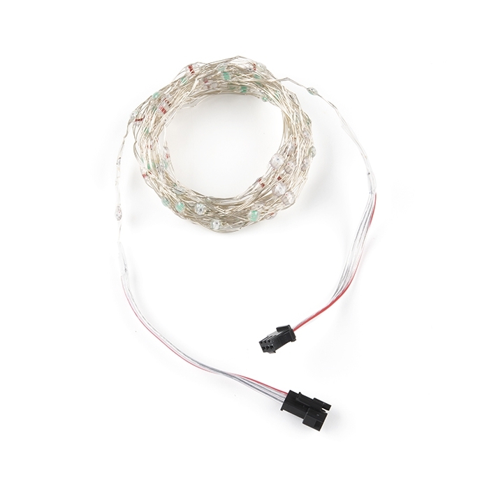
Affectionately dubbed "Fairy Lights" for their similar appearance, these addressable RGB LED string lights are a great way to light up any project.
Product Overview
Affectionately dubbed "Fairy Lights" for their similar appearance, these addressable RGB LED string lights are a great way to light up any project with no soldering required. The insulated strings come in 5m lengths with one RGB LED every 5cm for a total of 100 LEDs. These LEDs have an IP65 waterproof rating to protect your LEDs.
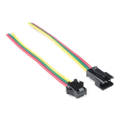
The string of lights terminate on either side with a locking 3-pin JST connector, one male and one female. The wiring and pinout is listed below.
- Red Stripe = 5V
- "White" (Middle) = DAT
- "White" (The Other Side) = GND (wire appears to be connected closest to the LED's dotted polarity marker side)
Similar Items
-
-
-
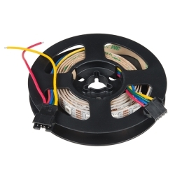 LED RGB Strip - Addressable, 1m (APA102)
Special Price Current price: $10.95 Regular Price Original price: $17.50In stock
LED RGB Strip - Addressable, 1m (APA102)
Special Price Current price: $10.95 Regular Price Original price: $17.50In stock


Hookup Accessories


Features & Specs
Color: RGB
LED Quantity: 100
Operating Voltage: 5 VDC
Control IC: WS2812
Light Spacing: 50mm
String Length: 5m
Wire Color: Silver
IP Rating: IP65
Documentation
Customer Reviews

Fairy Lights - Addressable RGB (5m)
$21.50
PRT-16792
Stock and Customer Discounts
$21.5 retail price.
Available Discounts
- $20.43 | 25+ units
- $19.35 | 100+ units