MIKROE Heart Rate Click
MIKROE Heart Rate Click is a heart rate monitoring and pulse oximetry measuring Click board™.
Product Overview
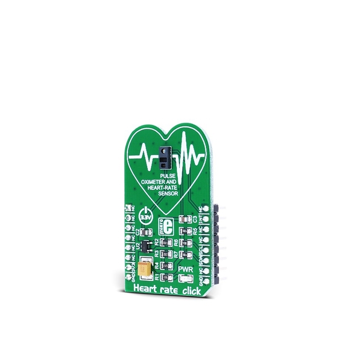
MIKROE Heart Rate Click is a heart rate monitoring and pulse oximetry measuring Click board™. It features an advanced oximeter and heart rate monitoring sensor, which relies on two integrated LEDs, a photosensitive element, and a very accurate and advanced low noise analog front end, to provide clean and accurate readings. It is enough to place an index finger on a top of the sensor to get both of the heart rate and blood oxygen saturation via the I2C interface. Features, such as the Ambient Light Cancellation (ALC) and the discrete time filters, ensure that no ambient light or 50/60Hz hum is interfering with the readings.
One of the more important features of this device is its low power consumption: it is possible to put the device into the Standby mode, where it consumes a very low amount of power. All those features make this Click board™ an ideal solution for various heart-rate and SpO2 related applications, as well as the development of new algorithms for reading blood parameters based on the red and infra-red absorbance properties of the human body, mainly for the arterial blood oxygen saturation (SpO2) and heart rate (HR).
The measurement of the hemoglobin oxygen saturation (HbO2) by measuring the absorbance of the red and IR light of the pulsating components was introduced in 1935 by Karl Matthes, a German physician. At first, there were no good photo-detectors and instead, the IR band, the green band of the light spectrum was used. As the technology advanced, more reliable methods of light detection were developed, and the green light was replaced with the IR light. Nowadays, advanced algorithms allow separation between the signals of the pulsating arterial blood and moving venous blood, allowing for more accurate and reliable readings. The Heart Rate Click features the MAX30100 a modern, integrated pulse oximeter and heart rate sensor IC, from Maxim Integrated.
This sensor features two integrated LEDs with the RED and IR LEDs, used to emit the respective wavelengths. The wavelengths of these LEDs are 660nm and 880nm, respectively. The reflected light is detected by a red/IR photo-detector element and sampled by a low noise delta-sigma 16bit ADC. The analog front end of the MAX30100 sensor features an Ambient Light Cancellation (ALC) section, which eliminates light pollution of the photo-detector element. The 16bit ADC is filtered by a discrete time filter to prevent 50/60Hz interference and hum. The output sampling frequency can be adjusted from 50Hz to 1kHz. There is also a temperature sensor, which can be utilized to compensate for the changes in the environment and to calibrate the measurements.
The MAX30100 sensor has the FIFO buffer, 16 words deep. The FIFO buffer stores the measured values and it can generate an interrupt when the buffer is full, allowing the host MCU to perform other tasks while the data is collected by the sensor.
The integrated LED drivers are operated with pulses of selectable width: pulses can vary from 200µs to 1600µs. The width of the pulse affects the available ADC bit depth and sample rate. The pulse width of 1600µs will allow maximal resolution of 16 bits with the highest sample rate of 1 ksps, while the pulse width of 200µs will only allow 100 sps for 16 bits resolution. Reducing the resolution to 13 bits will allow the full sample rate speed of 1ksps. Control of the LED pulse width, along with the programmable LED current, allows for an optimization of the measurement precision and power consumption. The power supply for the LEDs is taken directly from the 3.3V rail of the mikroBUS™.
To improve the measurements, the MAX30100 sensor employs a temperature sensor. This is a reasonably precise temperature sensor, which measures the die temperature with the accuracy of ±1˚C in the range of -40˚C to +85˚C. This sensor can be read from its data register and can be optionally used to compensate the sensor readings to the environmental temperature fluctuations. However, several other external factors can affect the precision of the device: besides the temperature, readings can be negatively affected by the excess motion, too. Also, too much pressure can constrict capillary blood flow and therefore diminish the reliability of the data. Those problems arise from the nature of the measurement method and should be considered while developing own application.
The MAX30100 sensor is supplied by the small LDO, which outputs clean and ripple free 1.8V for the internal logic and photo-detector element of the sensor. The input voltage is also taken from the 3.3V power rail of the mikroBUS™.
Besides the I2C lines of the sensor IC, routed to the respective mikroBUS™ SCL and SDA lines, the interrupt line from the sensor is also routed to the mikroBUS™ INT pin. By setting the appropriate INT register, the interrupt can be generated and enabled for 5 different sources: power ready, SpO2 ready, HR ready, temp ready, FIFO full. The power ready interrupt is enabled by default and can’t be disabled in software, but all other interrupts can be disabled or enabled, depending on the requirements of the application. Each interrupt is reported by the status bit in the interrupt status register and by pulling the INT line to a LOW logic state. The INT line is an open-drain, so it is pulled up to the HIGH logic level by the onboard resistor.


Features & Specs
- Interface: I2C
- Compatibility: mikroBUS™
- Dimensions: 42.9 x 25.4mm
- Input Voltage: 3.3V
Customer Reviews

Stock and Customer Discounts
Available Discounts
- $18.95 | 25+ units
- $17.96 | 100+ units