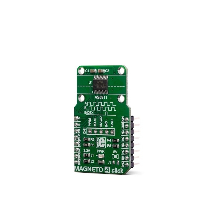
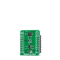
MIKROE Magneto 4 Click
Magneto 4 Click is a high-resolution magnetic encoder Click board™ which allows contactless motion sensing down to 0.5µm.
Product Overview
Magneto 4 Click is a high-resolution magnetic encoder Click board™ which allows contactless motion sensing down to 0.5µm. It features the AS5311, a complete integrated solution with Hall elements, low-noise analog front-end, and digital signal processing (DSP) sections, on the same die. Thanks to the internal DSP processing, the AS5311 can output the absolute movement detection over the serial interface as a bit stream, or as a PWM signal. The AS5311 IC also offers a high-resolution incremental output with the additional index option. The device is supposed to be used with the multi-pole magnetic strip or ring.
Magneto 4 Click is supported by a mikroSDK compliant library, which includes functions that simplify software development.
Besides the mikroBUS™, some of the pins are also available via the additional header on the Click board™ itself. Featuring very high absolute movement sensing resolution (12 bits over 2.0mm, 488nm), and incremental movement with the resolution of 1.95µm per step and traveling speed up to 650mm/second, this Click board™ can be used in robotics, as a servo drive feedback, micro-actuator feedback, as a replacement of optical encoders, and other similar high-precision motion measurement applications.
Magneto 4 Click is based on the AS5311, a high resolution magnetic linear encoder by ams which integrates Hall elements, a low-noise analog front-end, and a digital signal processing (DSP), on the same die. It is a System-on-Chip used for performing highly accurate measurements. It is designed to be used along with a multi-pole magnetic strip or ring. A pole length should be 1.0mm, while the strip should be placed about 3mm above the IC surface. The magnetic strip movement is translated into a 12-bit word on the output. In other words, the output is cycled from 0 to 4095 for each 2mm the strip moves. Also, this means that the movement resolution goes down to 488nm per LSB.
The AS5311 can output the movement data in several different formats: it can either output the bit-string over the serial interface, or by using the 12-bit pulse-width modulated signal (PWM). The pulse width of the PWM signal starts with 1µs and is increased for every 0.488μm. The maximum pulse width is 4095µs, which corresponds to a magnet movement of 2mm.
The incremental outputs allow this Click board™ to be used in place of a mechanical or optical quadrature encoder. These two outputs are phase-shifted for 90 degrees: the output A leads output B when the magnet is moving from right to left and vice-versa: output B leads output A when the magnet is moving from left to right. The resolution of the incremental outputs is 10 bits per pole pair (1024 steps), which results in a step length of 1.95μm. An additional index pin is triggered for each pulse pair. These pins can be disabled by using the Chip Select (CS) pin: whenever the CS pin is at a HIGH logic level, all the incremental output pins (A, B, Index) are disabled (fixed at a HIGH logic state). To prevent flickering in border-conditions, there is a hysteresis of 2 LSBs implemented.
The serial interface is very similar to SPI. However, depending on the correlation between the Chip Select pin and the clock signal logic state, two data modes are available: if the CS pin is pulled to a HIGH logic state (or floating) during the clock HIGH pulse, the AS5311 will report the magnitude (strength) of the magnetic field. Else, it will output the absolute linear position data. The output data contains both the magnetic/positional data bits (11 bits) and status bits (5 bits). The status report includes offset compensation status, "CORDIC" overflow status, linearity alarm status, and two magnetic field strength status bits.
The AS5311 can use either two hardware pins (MagINCn, MagENCn) routed to the additional header, or two status bits within the status report. These two bits/pins are used to describe the magnitude of the magnetic field. The datasheet refers to three different magnetic field magnitudes: green, yellow, and red. The green status represents the optimal strength of the magnetic field. The yellow status indicated that the obtained data may not be accurate, while the red status indicates that the magnetic field generated by the multi-pole strip or ring is weak and it is not recommended to use it.
For proper operation of the Click board™, a multi-pole magnetic strip should be properly placed above the IC so that it can move along x-axis only. To support correct placing, the Click board™ comes with four holes, which can be used to accurately position the strip in place. Please refer to the datasheet for more details about the magnetic strip positioning.
The Click board™ can work with MCUs that use with both 3.3V and 5V supply voltages. The power supply selection on this Click is a bit specific: to select 3.3V, both SMD jumpers grouped under the 3.3V label should be populated, while the SMD jumper under the 5V label should not be populated. Selecting 5V is done by removing two SMD jumpers under the 3.3V label and populating one SMD jumper under the 5V label. Please note that populating all the SMD jumpers at once may lead to malfunction.
Features & Specs
- Interface: GPIO, PWM, SPI
- Compatibility: mikroBUS™
- Dimensions: 42.9 x 25.4mm
- Input Voltage: 3.3V or 5V
Documentation
Customer Reviews
Stock and Customer Discounts
Available Discounts
- $28.45 | 25+ units
- $26.96 | 100+ units