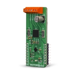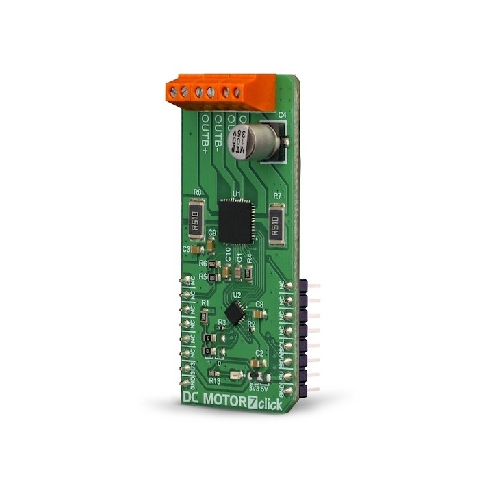
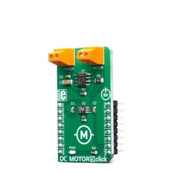
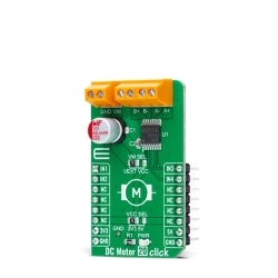
MIKROE DC Motor 7 Click
The main component of DC MOTOR 7 Click is the TB67H400AFTG, a PWM chopper-type brushed DC motor driver, produced by Toshiba.
Product Overview
DC MOTOR 7 Click is a dual brushed DC motor driving Click board™, featuring the advanced PWM chopper-type integrated DC motor driver, labeled as TB67H400AFTG. This IC can drive two brushed DC motors independently, using a wide range of supply voltages, while delivering reasonably high current to the connected DC motors. This is possible due to the low resistance of the integrated H-Bridges. In addition to being able to drive two independent DC motors, it can be used in a so-called large mode to drive a single motor, utilizing both bridges in parallel. This effectively doubles the amount of current it can deliver to the DC motor.
The Click board™ is supported by the mikroSDK compliant library, which includes functions that simplify software development.
Equipped with the specialized motor driver IC, DC MOTOR 7 Click can be used for any application that requires a simple and reliable dual DC motor support, including various RC cars and boats, small to medium-sized robots, drones, and similar applications. However, it can also be used for driving DC brushed motors in some more demanding applications, including air or water pumps, air condition systems, ventilation systems, handheld tools, etc.
The main component of DC MOTOR 7 Click is the TB67H400AFTG, a PWM chopper-type brushed DC motor driver, produced by Toshiba. This IC uses a proprietary BiCD manufacturing process, allowing this IC to be powered by a wide range of supply voltages, from 10V up to 47V. Due to a very low ON resistance of the MOSFETs, it can theoretically deliver up to 4A of current to the connected load. However, many external parameters affect both the maximum voltage and the current specifications, especially when the connected load is of a complex nature, such as the DC motor. This IC offers an additional, alternative mode, where it can use its internal H-Bridges in parallel, offering twice as much power for a single motor. Before attempting to connect a single DC brushed motor, please refer to the datasheet of the TB67H400AFTG for precise connection instructions.
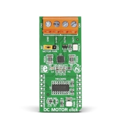
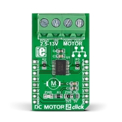
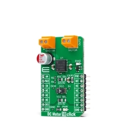
DC MOTOR 7 Click requires an external power supply for operation. The optimal voltage that should be used is 24V. Although the TB67H400AFTG driver has both thermal and overcurrent protection, it is just a temporary measure. A short-circuit at the output terminal may damage the Click board™. There are two output terminals used to connect DC motors, and a power supply input terminal, where the external PSU can be connected, with respect to the polarity marked on the Click board™ itself (bottom side).
Brushed DC motors are typically made with only two conductors, used to supply the motor with power, so even controlling the direction can be challenging in some situations. Therefore, a specialized driver circuit is required. The TB67H400AFTG utilizes two sensing resistors (one for each channel) in combination with an internally generated PWM signal, to regulate the current through the motor. This results in better efficiency, less heat dissipation, and provides control over the torque, direction, and speed of the motor.
Each motor is driven by the internal H-Bridge, which is controlled by the control logic section of the TB67H400AFTG IC. The motor control logic section regulates the current by opening and closing the specific MOSFETs of the H-Bridge, allowing the current through the coils to rise to a certain point (charging), to circulate between the coils and the driver until a specified point of time is reached (slow decay), and then to return the remaining energy to the power supply (fast decay). The whole cycle is timed by pulses of the PWM signal, which is derived from the internal oscillator.
The TB67H400AFTG exposes six control pins to the microcontroller (MCU): PWMA, PWMB, INA1, INA2, INB1, INB2. By changing logic states on these pins, the MCU can control both connected motors, independently. Besides a detailed explanation of the operating modes, the TB67H400AFTG datasheet also provides a truth table that explains the effects of logic states on these pins.
Since the TB67H400AFTG IC has six different control pins, an additional port expander IC is required to allow access to all these pins. PWMA and PWMB pins are routed to the mikroBUS™ RST and PWM pins respectively, while the rest of control pins (INA1, INA2, INB1, and INB2) are accessible via the PCA9538A, an 8-bit I2C port expander by NXP Semiconductors. In addition, the HBMODE pin used to select the single or dual operating mode (Large Mode or Small Mode), as well as the TBLKAB pin used to set the blanking interval, are also available over the PCA9538A IC. Logic states on the PCA9538A pins can be easily set over the I2C interface, allowing to quickly change states on all the control pins of the TB67H400AFTG IC by using a single command over the I2C interface. Please note that the state of the HBMODE pin should not be altered, once the Click board™ is powered up and initialized.
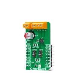
The peripheral I2C address of the PCA9538A can be changed. Two LSB of the I2C address can be set to 0 or 1, by switching SMD jumpers on the Click board™. This allows four different 7-bit I2C addresses to be selected, in the range from 0x70 to 0x73. The voltage level of logic signals can also be selected by switching the SMD jumper on the Click board™ to either 3V3 or 5V position.


Features & Specs
- Interface: GPIO, I2C
- Compatibility: mikroBUS™
- Dimensions: 57.15 x 25.4mm
- Input Voltage: 3.3V or 5V
Documentation
Customer Reviews