
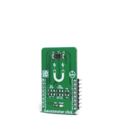
MIKROE Gaussmeter Click
Gaussmeter Click is a device that is used for measuring the magnetic field in X, Y and Z axes.
Product Overview
Gaussmeter Click is a device that is used for measuring the magnetic field in X, Y and Z axes. This Click board™ features the MLX90393, a micropower magnetometer based on the proprietary Triaxis® technology, from Melexis. It can detect the magnetic field down to 0.8 µT (8 mG) thanks to this technology. The integrated temperature sensor provides data for the thermal compensation, while the on-chip non-volatile memory can store the various working and compensation parameters, so they can be reused after the Power ON reset cycle (POR). The Click board™ supports both I2C and SPI communication protocols, allowing it to be interfaced with the wide range of different MCUs.
A range of on-chip features including low power consumption, programmable interrupt engine, 1KB of volatile + 1 KB of non-volatile memory, integrated thermal sensor, onboard digital filtering, high resolution sampling, and more, make this sensor a perfect solution for various low power applications used to detect a magnetic and electromagnetic field (EMF) presence along all three axes. It can be used to detect a rotary or linear movement of the magnetic elements or to measures EMF from mains electrical devices and other (very low frequency) EMF sources, such as from mains electricity, power lines, high voltage lines, transformers, and so on.
Gaussmeter Click employs the MLX90393, a micropower magnetometer based on the proprietary Triaxis® technology, from Melexis. This IC is based on the Hall effect principle, which allows it to detect very small fluctuations in the magnetic field. The Hall sensor plates, featuring the patented IMC technology, are located in the center of the die, which is located in the center of the package.
The measurement current, generated as a result of the Hall effect, is passed through the transimpedance amplifier (TIA) and sampled by the 19-bit A/D converter (ADC). The output is the truncated to 16-bits, by applying the bit-shifting operation, programmed by the user (RES_XYZ bits). This allows the range to be dynamically set, according to measurement conditions, leaving unused MSBs or LSBs out. Additionally, it is possible to set the TIA gain level in the range from 0 to 7 to best match the field strength. The value of the RES bits and the gain level both affect the sensitivity of the sensor. The MLX90393 datasheet contains a table with the RES and GAIN, and corresponding µT/LSB values.
When required, it is possible to set the oversampling rate of the ADC decimation filter. This will provide less noise and more consistent readings. However, oversampling affects the data acquisition time, as the sampling process has to be repeated a number of times, depending on the oversampling rate. If the fast response is required, the oversampling and digital filtering functions should be turned off.
The measurement is affected by the temperature. Therefore, the MLX90393 is also equipped with the temperature sensor, used to provide the required measurements. The thermal sensitivity drift compensation can be enabled by the appropriate bit in the configuration register. Two sensitivity drift compensation factors can be used, one for temperatures greater than the reference and other for the temperatures lesser than the reference value.
Wakeup on Change (WOC) mode is used to alert the MCU via the interrupt pin when certain conditions are met. It can be configured to trigger an interrupt on the INT pin if the difference between the reference measurement value and the current measurement value exceed a threshold defined by the user. The reference measurement value can be set in three different ways:
- The first measurement in WOC mode is set as the measurement reference value, which is then used for comparison.
- The reference value is always the previous measurement. Every new measurement sets the previous one as the reference value.
- Both the thresholds and the reference value are programmed by the user.
The interrupt is reported on the INT pin of the IC, routed to the INT pin of the mikroBUS™, and/or on the INT/TRIG pin, routed to the mikroBUS™ PWM pin (labeled as TRG), if it is configured that way. The INT/TRIG pin can also be set as the trigger input, by configuring the corresponding bits (TRIG_INT_SEL and EXT_TRIG). These pins are active HIGH.
Besides the WOC mode, there is also Burst and Single Measurement modes. Both of these modes can use the INT pin to signalize that there is a conversion data ready to be read. Once the MCU reads the data, the INT/Data Ready event will be cleared. The Burst mode provides data in programmed intervals, while Single Measurement mode will provide one reading when commanded, signal it via the INT pin and revert to IDLE mode, consuming less power.
The MLX90393 sensor contains 1KB of volatile (RAM) memory. This memory is used to store config parameters and register values, but also there are some free locations for storing user information, e.g. compensation values and similar. Besides 1KB of volatile memory, there is also 1KB of non-volatile memory. During the POR, the complete content of the NV memory is automatically copied to the RAM restoring the saved working parameters that way. There are also commands available for the user, in order to store to or restore RAM data from the non-volatile (NV) memory. However, it is not recommended to write to the NV memory area too often, as this type of memory has an inherently limited life cycle.
This Click board™ allows both SPI and I2C communication protocols. To select a proper protocol, the SMD jumpers labeled as SEL COM should be moved to the appropriate position (I2C or SPI). Please note that both jumpers need to be at the same setting (both as SPI or both as I2C).
The I2C address of the Click board™ is selectable by the onboard SMD jumpers, labeled as I2C ADDR. These two jumpers directly set the values of the LSB address of the IC. The 7-bit address of the device is 00011XXZ, where XX are the values set by these jumpers, while Z is the R/W bit.
Features & Specs
- Interface: I2C, SPI
- Compatibility: mikroBUS™
- Dimensions: 42.9 x 25.4mm
- Input Voltage: 3.3V
Documentation
Customer Reviews
Stock and Customer Discounts
Available Discounts
- $18.95 | 25+ units
- $17.96 | 100+ units