MIKROE BarGraph Click
BarGraph Click is a 10-segment bar graph display Click, which uses a high-quality bar graph LED display.
Product Overview
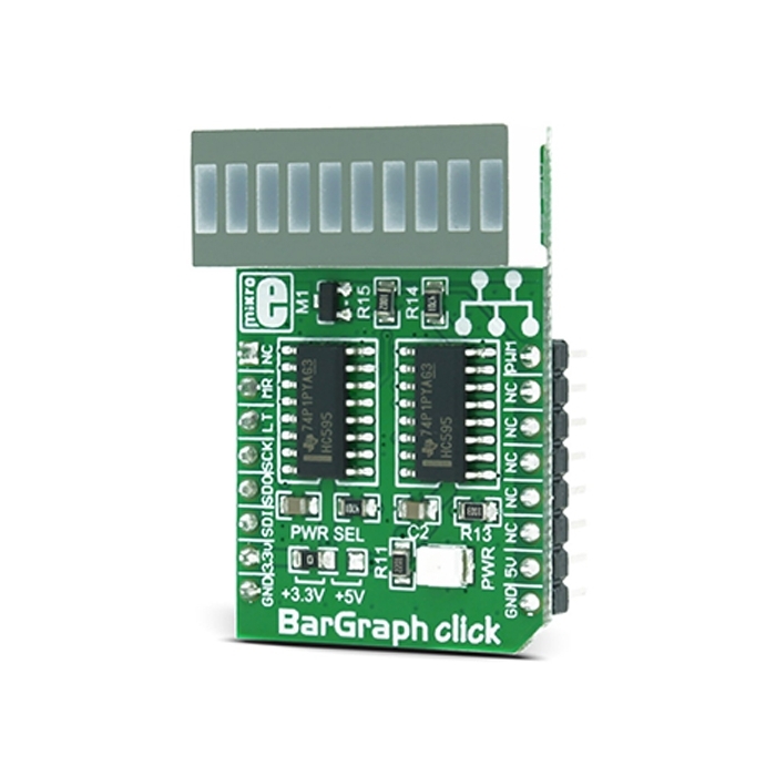
BarGraph Click is a 10-segment bar graph display Click, which uses a high-quality bar graph LED display. The bar graph display is a very popular device for displaying various properties, whether it be an audio level, current/voltage level, the position of the encoder, or any other property that can be displayed in a form of a bar graph. The segments of the onboard bar graph LED display are bright and uniformly colored, providing a nice and clean visual feedback.
Each segment is composed of a uniformly lit red colored LED, which draws about 20mA of current. The bar graph display light intensity can be dimmed by applying a PWM signal on the mikroBUS™ PWM pin. By utilizing two shift-register ICs, it is possible to program any pattern using these 10 segments via the industry-standard SPI interface. The Click board™ offers a lot of possibilities for building custom bar graph applications such as VU meters, status indicators, various types of gauges, and similar applications.
When it comes to driving an array of LED segments, using so-called shift register ICs is almost unavoidable. Due to their ability to be connected in cascades, they are commonly used for any type of LED segment array. This Click board™ uses two 74HC595, 8-bit serial-in, parallel-out shift registers with output latches, from Texas Instruments to drive the JSB-R102510ZR, a 10-segment bar graph array. The 74HC595 ICs are comprised of a D-type internal storage register, as well as the serial-to-parallel shift register, both 8 bits wide. Each of these registers has its own clock line, making it possible to clock in the desired data, and then clock it out to the parallel output pins.
The JSB-R102510ZR bar graph LED array has 10 red colored LED segments. Each LED has its anode and cathode routed out, making each LED element absolutely independent, so it can be used in any circuit configuration. However, the JSB-R102510ZR bar graph display is connected as display with the common cathode, meaning that all LED cathodes are connected to a single point. This LED cathodes common line (CC) is connected to the drain of the N channel MOSFET, while its source is connected to the GND. Driving this MOSFET via its gate through the PWM pin of the mikroBUS™ allows dimming of the LED segments. By changing the duty cycle of the PWM signal, it is possible to change the brightness of the XGURUGX10D bar graph display. The gate of this MOSFET is connected to the PWM pin of the mikroBUS™ and it is pulled to VCC, allowing display to work if the PWM pin is left floating.
The Click board™ communicates with the host MCU via the mikroBUS™ SPI interface pins. Two bytes of information (16 bits in total) are pushed through the serial data input pin (DS) of the first 74HC595 IC, routed to the SDI pin. The 74HC595 construction is such that after receiving 8 bits, clocking in one more bit will shift the existing 8 bits by one place, overflowing the last bit to the Q7S output pin, shifting it out that way. Since the Q7S of the first 74HC595 is connected to the DS pin of the second 74HC595, clocking 16 bits into the first 74HC595 IC will fill up both ICs with required data. Note that only two bits of the second byte will be used, since the second shift register only has 2 output connected to the bar graph display (8 from the first IC + 2 from the second).
It is worth mentioning that the Q7S of the last 74HC595 IC is routed to the MISO pin of the mikroBUS™, labeled as the SDO, allowing connection of multiple devices in cascade, building more complex setups. Adding more devices in cascade would require more 8bit words to be clocked into the first 74HC595 IC in the chain.
When the data has been clocked in, the SPI clock should be stopped, and the CS pin should be driven to a HIGH logic level. The CS pin of the mikroBUS™ is routed to the STCP pin of the 74HC595 ICs, and it is labeled as LT on the Click board™. A rising edge on the STCP input pins of the 74HC595 ICs will latch the data from their internal storage registers to the output pins, polarizing the connected bar graph segment anodes. The STCP pin is pulled to a LOW logic level by the onboard resistor. If the previously mentioned MOSFET is in conductive state, the current will be able to flow through the LEDs and the polarized LED elements will get lit.
The #MR pin is used to clear the data in the internal storage register of the ICs. The LOW logic level on this pin will clear the content of this storage register, but it will not turn off the outputs which are already activated. The #MR pin is routed to the RST pin of the mikroBUS™, labeled as MR and it is pulled to a HIGH logic level by the onboard resistor.
BarGraph Click is able to work with both 3.3V and 5V MCUs. The operating voltage selection can be done via the onboard SMD jumper, labeled as VCC SEL.


Features & Specs
- Interface: GPIO, PWM, SPI
- Compatibility: mikroBUS™
- Dimensions: 42.9 x 25.4mm
- Input Voltage: 3.3V or 5V
Customer Reviews
