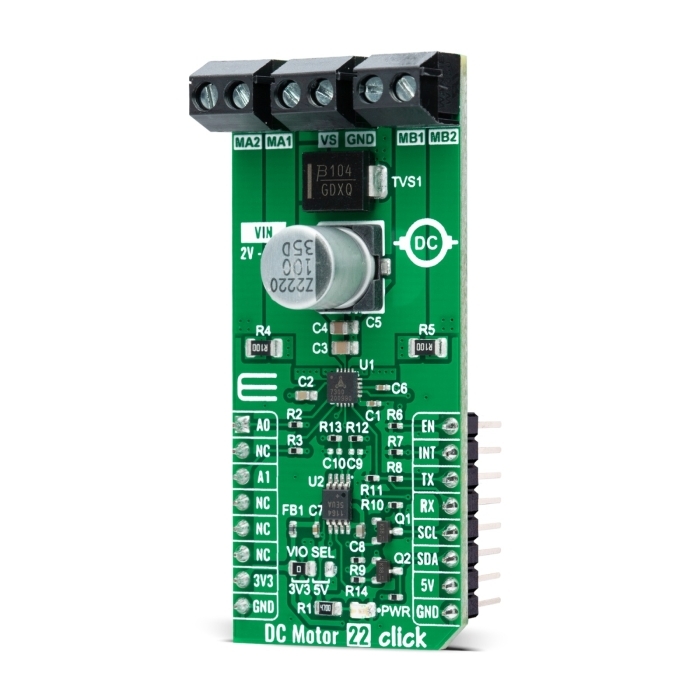
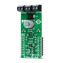
MIKROE DC Motor 22 Click
DC Motor 22 Click is a compact add-on board that contains a brushed DC motor driver.
Product Overview
DC Motor 22 Click is a compact add-on board that contains a brushed DC motor driver. This board features the TMC7300, a low voltage driver for one or two DC motors from Analog Devices. The TMC7300 is rated for an operating voltage range from 2V to 11V and operates up to two DC motors via simple UART control for direction, velocity, and torque. It also has a complete set of diagnostic and protection capabilities that supports robust and reliable operation, like short to ground protection, short to power supply protection and undervoltage detection. This Click board™ is suitable for driving DC brushed motors and targeted at the consumer and industrial market with end applications to low voltage equipment with up to 2A (2.4A) current per motor.
DC Motor 22 Click is supported by a mikroSDK compliant library, which includes functions that simplify software development.
DC Motor 22 Click as its foundation uses the TMC7300, a low voltage driver optimized for DC motor control from Analog Devices. The TMC7300 features high power density using integrated power MOSFETs and a complete integrated DC motor control logic for speed control, torque limits, and torque-controlled operation. It is rated for an operating voltage range from 2V to 11V and covers a broad spectrum of embedded applications with up to 2A (2.4A peak) current per motor terminal. This advanced driver ensures efficient and reliable operation for cost-effective and highly competitive solutions.
As mentioned before, the TMC7300 operates via simple UART control, with the default baud rate of 115200bps for the data transfer, which allows the operation of two DC motors or a single motor with a double current. The motor is operated by an internal PWM generator, where the desired duty cycle is programmed via the UART interface. The PWM acts like a dedicated voltage source for the motor, providing complete control over motor velocity and direction by setting the PWM voltage for each motor. This interface also controls the motor torque limit for both motors by setting a common current limit, allowing overloading to be avoided during acceleration safely or when a motor is blocked.
There is an addition to this Click board™'s current sensing capability for channels A and B. Based on the populated sense resistors R4 and R5 and the MAX11645 analog-to-digital converter, the user can obtain information on the current value of the channels, processing this information via the I2C interface. In addition, it also uses several mikroBUS™ pins. The Enable feature through the EN pin routed to the PWM pin of the mikroBUS™ socket offers a switch operation to turn ON/OFF power delivery to the connected load, while the A0 and A1 pins routed to the AN and CS pins of the mikroBUS™ socket are used to select the UART interface address.
It also has a complete set of diagnostic and protection capabilities that supports robust and reliable operation, like short to ground protection, short to power supply protection, and undervoltage detection reported through the INT pin of the mikroBUS™ socket.
This Click board™ can operate with both 3.3V and 5V logic voltage levels selected via the VIO SEL jumper. This way, it is allowed for both 3.3V and 5V capable MCUs to use the communication lines properly. However, the Click board™ comes equipped with a library that contains easy-to-use functions and an example code that can be used, as a reference, for further development.
Features & Specs
- Interface: I2C, UART
- Compatibility: mikroBUS™
- Dimensions: 57.15 x 25.4mm
- Input Voltage: 3.3V or 5V
- Supply Voltage: Min. 3.3V, Max. 5V
- External Supply Voltage Range: Min. 2V, Max. 11V
- Maximum Output Current: 2A
- Operating Temperature Range: Min. -40°C, Typ. +25°C, Max. +120°C
Documentation
Customer Reviews
Stock and Customer Discounts
Available Discounts
- $23.70 | 25+ units
- $22.46 | 100+ units