PCA9306 Level Translator Breakout

Replacement:BOB-11955. We've fixed an issue with a connection going to the enable pin as driving that to a high voltage can damage the PCA9306 chip. Go check out the new version! This page is for reference only.

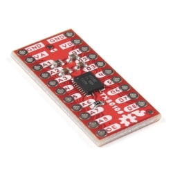
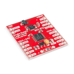
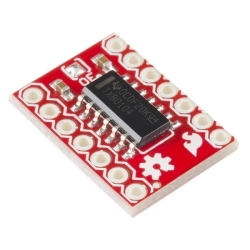
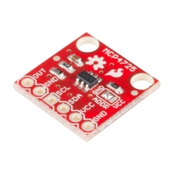
This is a breakout board for the PCA9306 dual bidirectional voltage-level translator. Because different parts sometimes use different voltage levels to communicate, voltage level translators can be the key to making different parts play nice.

The PCA9306 is a dual bidirectional I2C-bus and SMBus voltage-level translator that's operational on the low side from 1.0 V to 3.6 V and on the high side from 1.8 V to 5.5 V. Simply apply your low- and high-side reference voltages to the VREF1 and VREF2 respectively, connect your I/O and drive the Enable pin high to open bidirectional voltage translation without the use of a direction pin!

PCA9306 Level Translator Breakout Product Help and Resources

Core Skill: Soldering

This skill defines how difficult the soldering is on a particular product. It might be a couple simple solder joints, or require special reflow tools.

1 Soldering

Skill Level: Noob - Some basic soldering is required, but it is limited to a just a few pins, basic through-hole soldering, and couple (if any) polarized components. A basic soldering iron is all you should need.
See all skill levels


Core Skill: Programming

If a board needs code or communicates somehow, you're going to need to know how to program or interface with it. The programming skill is all about communication and code.

3 Programming

Skill Level: Competent - The toolchain for programming is a bit more complex and will examples may not be explicitly provided for you. You will be required to have a fundamental knowledge of programming and be required to provide your own code. You may need to modify existing libraries or code to work with your specific hardware. Sensor and hardware interfaces will be SPI or I2C.
See all skill levels


Core Skill: Electrical Prototyping

If it requires power, you need to know how much, what all the pins do, and how to hook it up. You may need to reference datasheets, schematics, and know the ins and outs of electronics.

2 Electrical Prototyping

Skill Level: Rookie - You may be required to know a bit more about the component, such as orientation, or how to hook it up, in addition to power requirements. You will need to understand polarized components.
See all skill levels


Comments

Looking for answers to technical questions?

We welcome your comments and suggestions below. However, if you are looking for solutions to technical questions please see our Technical Assistance page.

  • Member #124252 / about 12 years ago / 2

    I have used the $1.95 logic level converter for I2C between a microcontroller (5v) and MPR121 (3.3v Touch Sensor) and it works perfectly. So what is the difference with this one?

    • Tacroy / about 12 years ago / 2

      If all you're doing is 5V to 3.3V (or 2.8V or 1.8V), the logic level converter is a better deal. What this thing does is translate between a range of voltages on either side; for instance, you can use it to translate between, say, a 1.8V sensor and a 3.3V microprocessor, which is out of range for the logic level converter.

  • Grintor / about 11 years ago / 1

    Could you use this to connect a 3v analog device to a 5v IC? Or is this intended to just transmit digital signals?

  • Ed Criscuolo / about 11 years ago / 1

    Will this board perform level translation if the Enable pin is left open, or must it be pulled high externally? The circuit shows a 200k pullup on the chip's enable pin, but the product description says you have to "...drive the Enable pin high...".

    • Member #466285 / about 11 years ago / 1

      in the datasheet it says that EN has to be high for the IC to be active, as it's pulled high - like you said - you can leave it open or connect it to Digital I/O and pull high (only makes sense if you want to be able to drive it low/deactivate it).

  • CheetahShrk / about 12 years ago / 1

    So the schematic has GND on the PCA9306 on pin 4 while in all the datasheets for the manufacturers of the chip GND is on pin 1.

    • robotjosh / about 11 years ago / 1

      On all except the VSSOP8 package, which this appears to be (Fig 4).

  • Captain_Cankles / about 12 years ago / 1

    Ugh - thought I could use this to level shift between my Uno and an RN-XV WiFly Module. But now I find out this doesn't level shift the UART lines.

    I'm ready to give up. What should I use to get these two to talk?

    • Blacklab1 / about 11 years ago / 1

      Why do you think it will not shift UART lines? I am using a kissing cousin to the PCA9306 from DSS Circuits - The I2C Level Converter (TXS-0102) and had no problems with shifting between 5V and 3.3V in any direction. Cool thing about the TXS-0102: Since the TXS-0102 uses one-shots instead of standard MOSFETS it's effects due to larger buss capacitances is minimized.

    • jessejay / about 12 years ago / 1

      It's really not that hard. Just us the BOB-08745, and it will do exactly what you need if you know how to use it. I've done 5v ttl to 3.3v ttl using that, and even i2c also.

  • Captain_Cankles / about 12 years ago / 1

    This is frustrating – I’d love to buy an RN-XV WiFly Module for Christmas to interface with my Arduino Uno for a project in my car that will be controlled via my iPhone, but I’ve read so many things that say 2 way communication is difficult due to logic level conversion problems with BOB-08745. So I was considering BOB-10403 instead. 1)Does anyone have any experience using BOB-10403 with a RN-XV WiFly Module and an Uno? Is it fully capable of bi-directional logic conversion between the Uno and the RN-XV? 2)Are there any shields for the RN-XV WiFly Module that will work as expected and do the voltage and logic conversion for me? That would be my ideal device, but even the shields have issues. Why is this so complicated? I’d appreciate any help.

  • Progwhiz / about 12 years ago * / 1

    Further to show diagramatically

    3v to 5v respectively

    "Rx <-- SCL1" <-- SCL2 <-- Tx"

    . "Tx --> SDA1" --> SDA2 --> Rx"

    Is this correct if not please elaborate

    • This is only for I2C or SMBus, not serial.

      • Progwhiz / about 12 years ago / 1

        Ahh ok Kool, Thanks. One sligth off topic question. Why has the Xnee Series 1 Pro being limited to 10 units per customer? Thanks

        • Check the notes on the product pages:

          Note: Due to recent flooding in Thailand and the subsequent damage to the Digi factories, there may be long lead times on all XBee products and shortages until they recover from the damage.

          We don't want distributors buying up huge quantities to later resell them. They will be out of stock for a long while until the factories recover.

          • Progwhiz / about 12 years ago / 1

            Ahh, Thanks I didnt notice the note on that page, that sounds most reasonable and way bummer about the Factories

  • Progwhiz / about 12 years ago / 1

    So Guys to summarise in simple functionality terms a TTL 3v can speak to a TTL 5v IO where Rx/Tx is SCL1/SCL2 and SDA1/SDA2? Provided we supply the correct voltage at Vref1/Vref2 3v/5v respectively?

    • yes. (in simple answer terms) :-)

      • Progwhiz / about 12 years ago / 1

        Hi Robert, Many thanks for answering my initial query, I don't know how you keep on eye on things you must have mastered robotics and have at least 10 of you running around replying

        • haha. well technically my job is to manage all the products we carry, so I tend to know about them.

  • Member #15903 / about 12 years ago / 1

    A breakout for the MAX3377 (4 channel bidirectional level translator) would have been better.

  • Erdabyz / about 12 years ago / 1

    That design will eventually blow up! BEWARE! The 200k bias resistor is incorrectly sized for the stated voltage range. If you apply 5.5V with a 200k resistor then the pass transistor will basically blow for overcurrent and I'm not kidding. I recently made a design with a PCA9306 to which I was applying 5V at the high side. I didn't completely read the datasheet so I just used a 200k resistor. Lasted for about 2 hours and lots of time was spent on debugging because I wasn't expecting the PCA to be the broken component. I even changed it and the new one lasted seconds. Then I read the datasheet and changed the resistor to a more proper value (in order to be safe and considering that the I2C bus wasn't heavily loaded I chose 470k) and the circuit is working without any single problem since then. So please review the desing and either add multiple resistors so the users can select the appropriate one for their application or choose a higher value one that does a trade off.

    • SFUptownMaker / about 12 years ago / 1

      On page 10 of the datasheet, the design is specifically noted as using a 200k resistor for a 1.0V to 5.0V translation.

      I believe you are confusing the "enable" pull-up resistor with the pull-up resistors for the open drain outputs. The output transistor current is set by the drain-source on state resistance, the supply voltage, and the pull-up resistor.

      For now, our experiences in testing and using this device as well as interpretation of the datasheet suggest that 200k is the right value, and we'll continue to use that.

      • Blacklab1 / about 12 years ago / 1

        If I understand right the resistor value you have on the board is 30 ohms. That's far less then 200K ohms. I will admit my eye sight is not that good, but everything that I can find on SMT resistors says that 30 ohm resistor.

        • SFUptownMaker / about 12 years ago / 1

          SMT resistors are not universally labeled the same. Normally, yes, I'd expect a 300 labeled resistor to be a 30 ohm (30 x 10^0). For reasons I'm not privy to, this manufacturer uses a different convention, and the 300 label does, in fact, mean a 200k resistor- I have one on my desk and I just measured it to be certain.

          You'll note that the other resistors are labeled "01B". That's the code this manufacturer uses for a 1k resistor. I suspect it's to encode information more densely, so info about tolerance can be included.

    • if I'm reading the datasheet right, it looks like it won't tolerate anything above 5V.

      • The absolute max rating is 6V, and the datasheet mentions operating at 5.5V, so it should work at 5.5V. But these parts are not 100% tested by the manufacturer; so maybe you got a bad run of chips that are out of spec or are failing prematurely.

        • Erdabyz / about 12 years ago * / 1

          This is not about max. voltage rating, this is all about CURRENT!!!!!!!!!

          The 200k resistor biases a pass transistor that can't tolerate much more than 15mA. That's the driving current available for the bus. If you limit it too much, then you can't drive heavily loaded buses, but if you don't limit it properly, you basically blow the pass transistor.

          That resistor is suggested to have a value of 200k for a high side voltage of 3.3V and MAX CURRENT!!!. If you apply more than 3.3V to the high side with a 200k resistor you're overloading the pass transistor and if you go to 5V you'll blow it within minutes.

          This board should either have a higher value bias resistor to be keep pass transistor currents in the safe side at the maximum high side voltage, or have selectable resistor values to be able to optimize the current setting for some high side voltage values.

          Hope you've now understood what's the deal here. Surely the IC can tolerate 5+ volts, but under certain conditions that are not met in this desing. This design's absolute max high side voltage ISN'T limited by the absolute max voltage spec of the IC, but by the ABSOLUTE MAX CURRENT spec for the pass transistor.

          • Member #466285 / about 11 years ago / 1

            you mean micro ampere right? mA != µA U=R * I, 5V=200kOhm * I, I = 5V/200kOhm = 25µA > 15 µA.. guess you are right

          • Blacklab1 / about 12 years ago / 1

            Thanks for your explanation Erdabyz. I was just hoping for an easy solution for 5V to 3.3V Translator.

            So RobertC: It does not look too easy to change out that 200K resistor (300 SMD part). Could SF make one with 470K resistor for R3? Or give us an option that lets you select between 200K and 470K- like a solder bridge?

    • Blacklab1 / about 12 years ago / 1

      For us newbies here on this subject could you please walk us were in the Data sheet your looking at that showed you that you needed to double the resistor value? thanks Blacklab1

  • mpechner / about 12 years ago / 1

    What does this buy me over the $1.95 logic level converter, http://www.sparkfun.com/products/8745 ?

    • Kevin Vermeer / about 12 years ago * / 1

      It buys you:

      • An enable pin to isolate your bus (ex. to shield 100kHz i2c from faster stuff) - Mitigated by the breakout board.
      • A smaller footprint than multiple discrete transistors - Also mitigated by the breakout board.
      • Bidirectional translation - This is the real reason for this part, you can either side to, say, 3.3V and interface with both 5V and 1.8V busses.
      • A datasheet characterizing and specifying propagation delay, inline resistance, SNR, etc.

      Those are supposed to be bullet points, dunno what I'm doing wrong. HTML says they're bullet points, but that looks like a block quote to me. A little help, please?

  • MattTheGeek / about 12 years ago / 1

    Didn't i suggest this a while ago? (and even offer a breakout?)

Customer Reviews

No reviews yet.