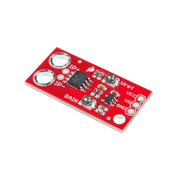
SparkFun Low Current Sensor Breakout - ACS712

This current sensor gives precise current measurement for both AC and DC signals. These are good sensors for metering and measuring overall power consumption of systems. The ACS712 current sensor measures up to 5A of DC or AC current. We added an opamp gain stage for more sensitive current measurements. By adjusting the gain (from 4.27 to 47) you can measure very small currents.

The ACS712 Low Current Sensor Breakout outputs an analog voltage that varies linearly with sensed current. To calibrate, first set the output offset to the desired level (with zero current on the sense lines, read output with a DVM). Then with a known current input (a 100mA limited supply works well for this), set the output deflection with the gain pot. Sensitivity is then calculated as (Vref - Vdeflect)/(current input).

The bandwidth on the ACS712 Low Current Sensor Breakout has been set to 34kHz to reduce noise when using at high gains. The full 80KHz bandwidth that the sensor is capable of can be recovered by removing C1. See schematic for more details.

SparkFun Low Current Sensor Breakout - ACS712 Product Help and Resources

Core Skill: Soldering

This skill defines how difficult the soldering is on a particular product. It might be a couple simple solder joints, or require special reflow tools.

1 Soldering

Skill Level: Noob - Some basic soldering is required, but it is limited to a just a few pins, basic through-hole soldering, and couple (if any) polarized components. A basic soldering iron is all you should need.
See all skill levels


Core Skill: Electrical Prototyping

If it requires power, you need to know how much, what all the pins do, and how to hook it up. You may need to reference datasheets, schematics, and know the ins and outs of electronics.

3 Electrical Prototyping

Skill Level: Competent - You will be required to reference a datasheet or schematic to know how to use a component. Your knowledge of a datasheet will only require basic features like power requirements, pinouts, or communications type. Also, you may need a power supply that?s greater than 12V or more than 1A worth of current.
See all skill levels


Comments

Looking for answers to technical questions?

We welcome your comments and suggestions below. However, if you are looking for solutions to technical questions please see our Technical Assistance page.

  • -------------------- Tech Support Tips/Troubleshooting/Common Issues --------------------

    Using the ACS712

    Previously, there wasn’t really a written tutorial on how to use this sensor. All that was available for using the current sensor was in the "SparkFun According to Pete #32 - Current Sensing” episode but it has been taken down. The reason for this was because a multimeter was used in the video that was breaking the Fluke patent law.

    Can be used for a low side or high side current monitor because it is an isolated current path. There might be tolerances, drift, noise, and deflection from the power supply or the Arduino’s ADC so you need to calibrate this sensor. Pete used a multimeter, Arduino, and a power supply to calibrate the sensor in the video. Vref was adjusted to a raw value of about 512 on the Arduino’s serial output to read positive and negative current. It was a little noisy. He then adjusted the gain to amplify the signal to read.

    Sensitivity

    The sensitivity of the IC is about 185mV/A and you have a 4.27 gain. So you would get 0.78995 mV per A.

    Maximum Gain

    Setting the gain sets the maximum current deflection.

    Example

    Tutorial Examples:

    http://embedded-lab.com/blog/a-brief-overview-of-allegro-acs712-current-sensor-part-1/

    http://henrysbench.capnfatz.com/henrys-bench/arduino-current-measurements/the-acs712-current-sensor-with-an-arduino/

    https://www.youtube.com/watch?v=etsIFUUhO6I

    FAQ

    ACS712 => http://www.allegromicro.com/en/Products/Current-Sensor-ICs/Zero-To-Fifty-Amp-Integrated-Conductor-Sensor-ICs/ACS712/ACS712-ACS713-Frequently-Asked-Questions.aspx.

  • n1ist / about 6 years ago / 1

    Do NOT use this for line voltage (120V or 230V) or high voltage DC. The spacing between the ground pour and the current measurement pads and traces is way too close for safety.

  • fkoran / about 7 years ago / 1

    very small currents

    Would this include sleep current on an MCU, in the range of 10uA to 10mA?

  • ebader18 / about 13 years ago / 3

    What is the sensitivity of that current sensor with the op-amp?
    miliamps? microamps?

    • Macka / about 13 years ago / 2

      From the data sheet, 66 to 185 mV/A, now multiply it by your gain factor (4.27 to 47)

  • Fantom1107 / about 13 years ago * / 2

    Yes

  • Member #640610 / about 9 years ago / 1

    im trying to measure a current of 0.4 A but when i turn it up my Vout doesnt chqnge at all. Also when i measure the ic pin 7 its the same surrent as on the output pin which isnt possible. What do i do? and is there a possibility that its broke?

  • Member #635277 / about 9 years ago / 1

    Hi, I want to measure 5A output of a 220V 150/5A current transformer via this module. How do I do this?

  • Member #564740 / about 10 years ago / 1

    In case this saves someone some time (since I just worked this out the hard way)... you can't use a current detector with a stepper motor. Stepper motors run at full current all the time (so they can lock their position) so you can't detect (for example) an increase in current draw with an increase in load for current-control of the motor.

  • Member #162165 / about 10 years ago / 1

    I need a 1 or 0 logic output from a 1amp electromagnetic device. A 1 is above 3v3/2. Does anyone know if the gain on this device will allow that type of range? I understand that 0amps = 2.5V. So I am assuming that the output could be dropped with the output offset, then the gain could easily push it over 3v3/2

  • Member #557564 / about 10 years ago / 1

    hi, I'm using the normal ACS712 breakout but I've found non-linearity below 250mA. I have to measure low currents so I was thinking...but if I amplify the Vout then I'd amplify the non-linearity as well!

    any suggestions? (and....is it normal that ACS712 is not linear below 250mA?)

    tnx, G

  • Member #500929 / about 10 years ago * / 1

    Hello

    i have the 5A version of ACS712, and i would like to measure 50mA from a LED stripe, using Energymicro STK 3700. after making all connection the GND Pin and the VCC pin of the ACS712 are signaling a contact that mean something is wrong with my circuit.

    As I am a begginner,could someone please tell me how i could design my circuit to avoid this problem ?

    I use a 12V power supply for the LED, and a 5V power supply for the ACS712 separately.

    Thanks

    • That's a fairly big answer, especially for this comment section. Can I get you to contact tech support or post in the forums? You'll have a lot better success that way.

  • IQLogic / about 10 years ago * / 1

    R3 & R4 values please :)

    EDIT Both 10K

  • Member #461283 / about 11 years ago / 1

    Do you have the version 20 A (ACS712ELCTR-20A-T )? Instead of the chip ACS712ELCTR-05B-T.

  • Member #204950 / about 11 years ago / 1

    I have a line that sometimes carries 230V AC and other times ~400DC when it is rectified. I could not identify from the datasheet if AC and DC have different properties for this sensor, if voltage is much of an issue or if it is ONLY the current it senses...

    I will probably swap out the op-amp for a peak detector amplifier, I just need a Current/No Current detector that does not need re-calibrating with every current change . Can anyone advise me!!

  • Member #276435 / about 11 years ago / 1

    This may sound a little dense, but i'm not an EE...i'm in marketing! Can this breakout be used to accurately sense 4-20 mA signals from a loop powered pressure sensor (powered by 12vDC, 2A)?

    • KloudVine / about 11 years ago * / 1

      Sensitivity on this is 185 mV/A with 21mV of noise. Page 5 of the datasheet. 20mA results in a rise of 3.7 mV. Since SF has enabled the noise filter, lets say this is reliably measurable (YMMV aka: no - probably not that reliably measureable).

      That results in roughly 174mV at 20mA (at max gain of 47x). Arduinos can measure from 0 to 5V with 10 bits or 4.8mV. This ends up with roughly 30 measurements in 4 to 20mA. Not great precision.

      Tl;dr: No. This is not the right way to measure the current output.

      You can more easily measure your output with a precision resistor. Pass the current from the sensor through a resistor (say 100Ohm). That means at 4mA you have a voltage of 400mV across the resistor and at 20mA you get 2000mV across the resistor. You could measure this with the arduino directly, or if you wanted more precise measurements, measure it after amplification with an op amp or using an external adc.

      See: http://forums.adafruit.com/viewtopic.php?f=8&t=12473

      • Krb686 / about 10 years ago / 1

        Don't forget, you can supply a Vref to the arduino the change its analog read scale. Supply say a 500mV reference, and you've got ~350ish measurements in the 0 to 174mV range.

  • Member #406212 / about 11 years ago / 1

    Lots of questions here, where arethe answers? I want to use this board to measure 120VAC that is less than 3 amps. Hard to tell from the schematic how this is can be done, do i need to rectify to DC prior?

  • Member #367986 / about 11 years ago / 1

    I'm doing a project to measure a very small current. I need to measure currents of 0.1mA to 0.8mA ....

    I've spent researching. I Don't understand what value require to set "Vref" and "GAIN" of the tablet ACS712 ...

    I am using this code: https://forum.sparkfun.com/viewtopic.php?f=6&t=33605&p=150265&hilit=acs712#p150265

    Someone could help me, please ...

  • nemoskull / about 12 years ago / 1

    i wonder if you can read a 0.5mah change with this. if you could, this could be used for a Wide Band O2 sensor.

  • Member #275028 / about 12 years ago / 1

    I would like to assemble a similiar board replacing the trimmers with fixed resistors. Which is the range of the two trimmers R3 and R4?

  • MTS / about 12 years ago / 1

    I purchased 30 of this for a project. My thought so far are as follows.

    With a line unloaded there is a lot of noise in the system. You will have to sample the sensor at high rate and then average out so many samples to get something reasonable. I have an idle system at 20mA and it's very difficult to detect, however when running it at 300mA then once can see the change in output voltage from the current sensor.

    Arduino Uno Analog In from Vout on Current Break out board.

    To calibrate, I used a multimetere and connected it in series with this sensors with the load turned off. Using the map() function in Arduino IDE, I remapped the analog 10-bit back into voltages, then maxed out the Vref. Read it's value in arduino (mine was 4.93V) the lowered Vref and keep gain as high as possible. Once your arduino reads Vout as something lower than 4.93V, you can lower Vred (Slowly) till you have a voltage you want to work with (I used ~2V) then apply a current. (20mA) and check out how much Vout changed in arduino. (Mine changed from 2.0 to 1.98V) I did noticed that with this method you will get an inverting effect. Meaning more current actually lowers the voltage. This can easily be fixed with map() again.

    So far I wasn't able to really measure 20mA decent since all the noise causes lots of errors in reading. Sampling at 1kH and then averging every 1/4 of a second should give decent results.

    • Frustrated / about 12 years ago / 1

      Check the datasheet because that's normal. See the FAQ but due to the internal noise the smallest amount the ACS712 can measure is between 100ma and 500ma depending on your bandwidth. You might want to think about a current sense amplifier instead.

    • MTS / about 12 years ago / 1

      Forgot to mention. my system that this is connected to uses 28V.

  • CatsWhisker / about 12 years ago / 1

    It appears that this breakout board could easily have been designed to plug straight into a breadboard by simply shifting one set of header pin holes by 0.05".

    Could this please be a suggestion for a new version?

    • DanZ / about 12 years ago / 1

      I logged in to comment on just that.

      When you plug it in to a breadboard with just the little ip-/ip+ the board is crooked.

      If the eagle files were posted I'd just submit the changes.

  • Member #275028 / about 12 years ago / 1

    I still did not get how to tune this sensor.

    I've tried to set the vref in such a way to read 2.5V on vout when no current is flowing trough the sensor. The I apply a small current (e.g. 50 mA) and I set the gain in such a way to get a reading of about 4.5V.

    However I would like to have a vref very small and to use ideally the full range 0-5V to measure the current. I then tried to set the vref to 1V and the gain to the maximum, but all I can get is a reading of 1.37V in the vout when the same 50mA is flowing trough the sensor.

    Any idea?

    • Member #335744 / about 12 years ago / 1

      why? What do you need to do? My view point you need a range value like 1,27 untill 3,0 volts. why do you need a exactly five volts?

  • djdan / about 13 years ago / 1

    Hey All, got a question about using this board. I want to use this to measure the current in a 120V AC line. The current should always be under 5 Amps. My question is about the output, since the bandwidth of the board is limited by the filter capacitor to 34Hz, does that mean that for a constant AC current say 2cos(120t), that the output would be a DC signal proportional to the average current in the AC line? Or would I be getting an AC signal proportional to the instantaneous current in the AC line?

    • Progwhiz / about 12 years ago / 1

      Hi All,

      Is it possible to use this sensor to measure the input voltage being supplied to the controller to which this sensor is attached? Or is this only used to measure voltage/current on everythign but the power source to allow the sensor to operate?

      Thanks

  • oceanwanderlust / about 13 years ago / 1

    Am I correct that this device should be able to easily detect an existing 24vAC doorbell without the need for a $30+ ELK 930 or diy multiple component bridge-optocoupler-etc design?

  • walnut49 / about 13 years ago / 1

    This board can measure both forward and reverse currents, correct?

  • I need a sensor for down to 10 microamps on a 0-5V system will this device work?
    What is the highest sensitivity it can reach?

  • Member #76446 / about 13 years ago / 1

    Some better specs would be nice. It looks like this board comes with the 5 amp version of the ACS712?? is that correct??
    and if i read the data sheet correctly. the 5amp version has a 185mv per amp output?? which is then feed to an op-amp stage with a min of gain of 4.27 so if i am figuring this out correctly.
    .185x4.27 = 0.789mv per amp minimum output correct??
    and if 5V is the maximum output, then with the gain set for 47 then max output would = about 0.58amp measured???

    • Member #335744 / about 12 years ago / 2

      friend, my view point, we use this only with very low currents. I need to use this to measure currents near 0.10mA.

      example: I know that for one 1A = 1000mA. each 1000mA = 0.185mV Arduino with 10 bit value = analogic read means = 5v/1023 bit = 0.0048V

      acs 712 = .185/1000 = 0.000185 = I need 0.10mA = 0.00185V this is very low to me and the arduino, to arduino measure this value I will need at least 0.20mA.

      So I can use this Amp to increase the number near to 10 times.

      If we have currents near to limit 5A we must make sure the output value, or we will damage the Analogic reader ( in my case arduino).

      see you

  • amir15 / about 13 years ago * / 1

    Hi guys. i need to sense currents as low as 0.08 amper. can i do it using this product? any better suggestions?
    tanx.

  • Faze / about 13 years ago / 1

    Stupid Question, but would this work to take readings from a standard PH probe (my current project is a water PH tester)

  • Member #147958 / about 13 years ago / 1

    What are the values of the GAIN and Vref pots R3 and R4?

  • mr.marmot / about 13 years ago / 1

    Would it be possible to combine this board with something like this: 582-1004-ND to non-intrusively sense appliance current use? I'd like to be able to tell when my washing machine is running.

    • Jeff23 / about 13 years ago / 1

      Yes it is, you need to measure the current running through the burden resistor for the secondary side of the current sense transformer. That being said, you could probably configure the burden resistor network to give you an analog to digital converter friendly voltage, allowing a direct measurement.

  • arkhos / about 14 years ago / 1

    What kind of waveform, AC/DC value (Pk-Pk or RMS) this sensor outputs? Can an RMS value be set using the trimPots?

  • Blizok / about 14 years ago / 1

    Input holes are 2mm (as i see of documentation), screws 2-56 are 2.2mm diameter, which screws should i use for input connection?

  • Smoerijf / about 15 years ago / 1

    I got the simplified version, without opamp, and the holes on my board are 2mm. More then width enough for 5 amps.

  • Member #58365 / about 15 years ago / 1

    Have you used this for monitoring current to a device using AC mains (120v ac)? How big are the holes for the input lines -- i.e., what gauge of wire will fit into the holes?
    Thanks.

Customer Reviews

3.3 out of 5

Based on 9 ratings:

Currently viewing all customer reviews.

3 of 3 found this helpful:

having real trouble, must be something I don't understand

Have spent a few hours with this, looked over the wiring many times, read the schematics and datasheet...I am not able to get any signal out of this for any current I put through it. Have tried a wide variety of voltage and current seeing from very small upwards to as large as the specs allow. Trying to to see anything, but I don't. Adjusting vref and gain shows effect, but not relative to whether there is current going through it or not.

Have also bought more than one and tried more than one. Same issue. I am open to it being something I am not understanding but I've put in a fair amount of time into this and am not seeing it.

Issue for me with this device is that there are no "getting-started" docs or project samples specific to it...any project-oriented documentation you find has to do either with the ACS712 or another breakout board using it. Of course one can and should be able to extrapolate from that board to this one, but when things don't work at all, you can not be sure where your problem lies.

Greetings. Sorry to hear you are having issues with several of these products. We are going to contact you privately to see if we can assist you with your setup and get your project up and running!

1 of 1 found this helpful:

Preliminary checks all satisfactory

I would have given this 5 stars... but I haven't investigated it thoroughly yet.

"Just worked" for me... when I changed current through device from 180mA to 500mA, I saw a swing on the output voltage from 1v7 (1.7 volts) to 3v8..

In other words, a change of 320mA in the current though the device gave me a 2v1 swing in the voltage on the analog output.

If you want to watch something that may range over, say, 10mA to 25mA, then this isn't the device for you... but it doesn't claim to be. If the current you need to watch stays below 5A, and will swing by, let's say 500mA... then it might be the one for you.

Also written up at...

http://www.arunet.co.uk/tkboyd/ec/ec1SensCurr.htm

=== Make you laugh? I had a pretty rough and ready test rig lashed up. I hadn't paid much attention to the precise specs of the pot I was using. I couldn't figure out why the output was taking time to settle to a consistent value. Then I burned my finger on one of the pins of the pot. I was putting more current though it that it was rated for. It was getting hot. And thus its resistance was changing, and the current was changing... so it SHOULD have been drifting... as it was.

2 of 2 found this helpful:

What actually is low current?

Had to replace the hall effect sensor by a simple shunt resistor to get precise current measurement: the hall effect sensor is very noisy and will work for current measurements over 100mA... Even with the replacement, it's still a good pcb (op-amp + gain and offset on a small pcb... good enough!

1 of 2 found this helpful:

Works as Expected

Bought this board to measure power from one of the Large Solar Panels on this site. It has worked as expected and was very easy to set up. The voltage signal does carry more noise on the output but that is likely due to the amplifier used.

One recommendation: mounting holes (at least two) would be nice. This board is floating in space in my project and is suspended by the solid core hookup wire.

0 of 1 found this helpful:

Handy little sensor

Great little sensor for the application needed. Thanks Sparkfun!

0 of 1 found this helpful:

unreliable / too complicated

  1. in my board I received, it had different potentiometers than in pictures, in my case models are ones with metal plates. I hadn't suitable instrument to easily regulate them, so I broke Vref potentiometer after testing it. It started to output jerky values until it was either 0 or 5v. I succesfully replaced it with external 10k pot.

  2. I think it's not good idea to calibrate, based on external current source. As a beginner I don't have such sources, and second, it adds further imprecision.

  3. I think that manual potentiometers consume too much of my time, so after this experience, my confidence is that digital pots are better and more reliable. Their cost is not too high for comfort they provide.

  4. In the end I soldered wire directly to ACS712 Vout pin. This board has 5amp version with 185 mV/A sensitivity. At least, I can be sure about precision of this.

  5. 4.1 Accordingly, Arduino 10-bit ADC is unsuitable for such small measurements. My calculations:

    volts at 0 current = midpoint of 5V, it's 2.5 v

    sensitivity 185 mV/A.

    range is 5 A, so

    5 * 185 = 925 ma, on -5A gets 2.5 - 0.925 = 1.575

    on 5A gets 2.5 + 0.925 = 3.425 volts.

    ADC works in range 0...5V (it's important to provide stable 5V to both Adruino AREF, this sensor, and/or external ADC). It can be achieved using voltage stabiliser, I used L7805ABV feeded with 12V, and got stable 5.03 v.

    To find out real precision I can get from 10-bit ADC, I have to fill this "5V window" with 185 mV "parts". From there, I can calculate, how much milliamps I can measure with 1 part from ADC value.

    So, 5000 mV / 185 mV = 27,027 "fill ups" or "amps to be seen" projects onto 1024 values provided by ADC. It's 27.027 / 1024 = 0,026. 1 ADC value part can represent 26 ma.

    I want better precision, so I ordered 16-bit ADC. I'm waiting for it but math shows that:

    16 bits provide about 65000 values.

    27.027 / 65000 = 0,0004158 or 0,4158 ma. Much better!

    1. Precision can even further increased by this logic: Default 185 mV/A measurements in 5V window are leaving 1.575 volts unused in this range, at both ends. 5 amps generate 925 mV. 2.5 / 0.925 = 2,70. It means that I can stretch 925 mV up to x2.7 times to fill 5V window almost fully, so ADC can use it. This can be achieved using op amp.

    ah, here is my detailed logic for calibration of this board. It's how I understood, but as I wrote, I didn't use and validated this method fully:

    vin = 5.03

    desired max range = +/- 2 A

    so vref should be about in midpoint of Vin, about 5.03 / 2 = 2.5

    set gain to minimum.

    current reference = 83.46 ma

    reference to range ratio = 2000 / 83.46 = 23,963575365

    reference current in volts = 2.5 (full range) / 23,963575365 = 0,104325 volts

    desired volts after gain correction should be 2.5 - 0,104325 = 2,395675 v (on positive current)

    sensitivity = (full range volts * 1000) / full range amps

    = (2.5 * 1000) / 2 = 1250 mV/A

Good Low current Sensor, but a few updates could make it even better.

This is a very cool way to for measuring low to moderate currents with minimal (~ 0) voltage drop. There are two single turn pots to set the sensor gain and offset. Over all it works well.

Here's some suggestions that would make it even better!

1) The adjustment pots work okay but I feel that for a minimal impact to costs, these should be changed to 10 turn pots as this would make calibration and setup much easier. Perhaps just adding some additional layout holes for typical 10 turn pots would be enough so those of us that need this option, could easily change out the singe turn pots with 10 turn versions.

2) It would be handy if SparkFun would add extra through holes in the circuit board so that the customer could place a cap of their selection to set (reduce/increase) the amplifier roll off point. How about extra holes for personalizing the gain resistors as well?

4) Lastly, I like to see mounting holes on all circuit boards and modules. I suggest 4-40 clearance holes as a mounting option.

Thank you for your input. Our engineers keep an eye on our product reviews, and tend to take suggestions into consideration. Thanks again, and Happy Hacking!

0 of 1 found this helpful:

Susceptible to iron & magnetic field orientation

The output is pretty noisy and it's hard to tune the gain and voltage offset because the metal screwdriver affects the Hall-effect sensor.