Evaluation Board for MLX90614 IR Thermometer

**Replacement: **SEN-10740. The latest revision corrects the silkscreen error on the FTDI header. We've also added pull-up resistors to the I2C lines. This page is for reference only.

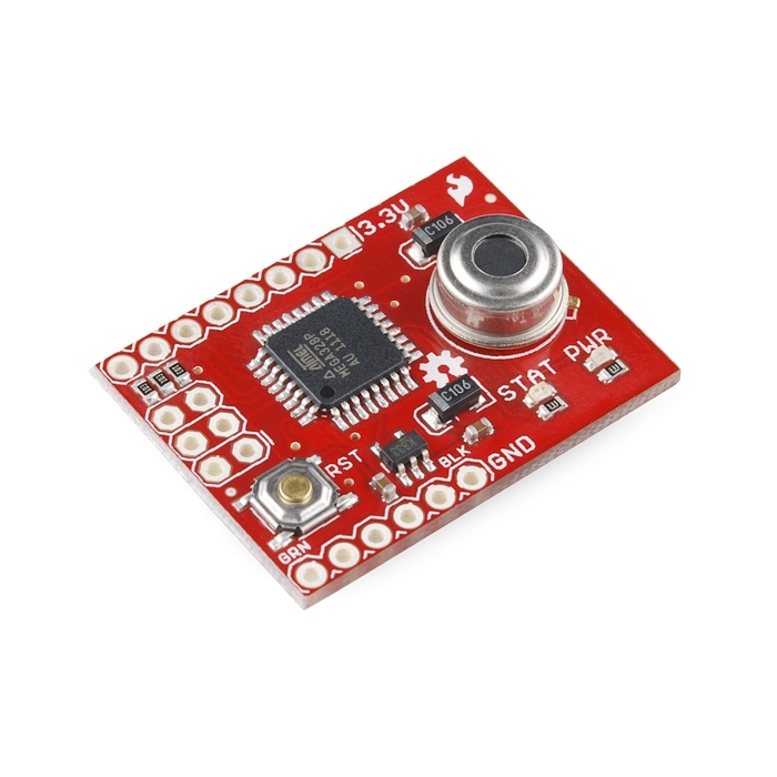
This is an evaluation board for the MLX90614 IR Thermometer. The sensor is connected to an ATmega328 running at 3.3V with a STK500 (Arduino) 8MHz bootloader. Code can be loaded through the FTDI basic interface and the Arduino environment..

The MLX9061 sensor is a high precision, small size, single zone IR thermometer with an optional SMBus (two-wire) or PWM interface. The ATMega328 comes with demo code that gives a temperature readout in degrees F at 38400bps. You can use a 3.3V FTDI Basic to connect to the board.

Note: The label on the FTDI header is incorrect. It should read VCC instead of 3.3v. We will fix this error in the next revision.

  • ATMega328 w/ 8MHz STK500 (Arduino) bootloader
  • MLX90614 IR sensor, 3V version
  • Power and status LEDs

Evaluation Board for MLX90614 IR Thermometer Product Help and Resources

MLX90614 IR Thermometer Hookup Guide

October 29, 2015

How to use the MLX90614 or our SparkFun IR Thermometer Evaluation Board to take temperatures remotely, over short distances.

Comments

Looking for answers to technical questions?

We welcome your comments and suggestions below. However, if you are looking for solutions to technical questions please see our Technical Assistance page.

  • Member #386699 / about 11 years ago / 1

    I have question??? How i can connect this evaluation board to PC or LCD to show temprature.???

  • A comment from our customer Jay:

    I bought the MLX90614 board last week and its working great, I'm using the firmware it came loaded with out of the box. In addition to changing the header "3.3V" to "VCC", the TX & RX labels and schematic net names are swapped. When looking into a device, TX should be TX from the device, RX should be the RX of the device.

  • quasidart / about 12 years ago / 1

    About that note at the end of the product text:

    Note: The label on the FTDI header is incorrect. It should read VCC instead of 3.3v. We will fix this error in the next revision.

    Is that just for naming consistency w/ the FTDI pinout, or does it imply that the board can also be powered safely when the VCC pin = 5v? (If you'd prefer, I'd also be happy with the name of the part used for the board's 3.3v regulator, so I can find out on my own.)

    Thanks!

  • theuser20 / about 12 years ago / 1

    For Linux Users.

    1) download code. 2) extract code. 3) open command line change to root, ie su 4) cd to sub directory alronzo* then cd to IR_eval 5) run the command "make" 6) plug in your IR board to your ftdi basic and plug into pc. 7) open up arduino to check the location of device should be something like /dev/ttyUSB0 this will be option -P below. 8) close arduino program. 9) run on the command line avrdude -c STK500 -p m328p -P /dev/ttyUSB0 -b 576000 -U "main.hex"

    10) open up arduino again select ATmega328 for the board type 11) open up serial monitor and change baud rate to 38400 baud

    should see stream of temperature values in F.

  • Promptcritical / about 13 years ago / 1

    Arduino
    First. http://bildr.org/2011/02/mlx90614-arduino/
    Then
    http://www.phanderson.com/arduino/mlx90614_1.html
    http://interface.khm.de/index.php/lab/experiments/infrared-thermometer-mlx90614/
    https://bitbucket.org/alt36/ami_arduinomisc/src/2203858692a9/pm418-arduino-sketchbook/ir_temp_sensor/ir_temperature_sensor_with_ambient_temp/ir_temperature_sensor_with_ambient_temp.pde

  • Promptcritical / about 13 years ago / 1

    I have some of the 10' FOV 3.3v 90614's. Coulb I get just the programmed breakout board?
    Mike

  • strangers / about 13 years ago / 1

    Does anybody have any code for this thing, or any resources on how to get it to work? I can't find anything for it.

    • mjkuwp / about 13 years ago / 1

      'strangers'; according to the description the product ships with working code. You need the FTDI board in order to hook it to your computer through USB if that's what you are after.
      I was able to download the code by following the "Example Code" link but it's not very Arduino-friendly..makefile and such for people who know their way around compilers. I'm not sure but maybe the code can be included in an Arduino sketch - essentially adding the I2c as a library... but I am guessing!!!
      another place to start would be to use the Wire library and the Arduino environment along with information from the Melexis datasheet. It's pretty technical but what I think is going on is that the Sparkfun board is using I2C as 'close enough' to the SMBUS protocol that the Melexis unit uses. I've read elsewhere that this works better at 3.3V than it does at 5V due to slightly different specification difference between those two standards (I2C and SMBUS)
      note: I have a Parallax module that includes this Melexis sensor and that project has led me to do the research ... and is why I am claiming to know a little bit...but not yet as much as I would like.

  • bidontr / about 13 years ago / 1

    i saw rx/tx pin on this board does this means that i can connect it to my arduino uno and simple point it to some heat and get the data?

  • KineticaRT / about 13 years ago / 1

    The example code comprises C source and header files.
    Is an Arduino Sketch available from anywhere that has the same functionality?

    • Promptcritical / about 13 years ago / 1

      Yes. There is a zip file going around on the internets with the name melexis_90614 or something close and it contains the sketch and custom i2c library.

  • rmd6502 / about 14 years ago / 1

    It would be interesting to set the PWM period to 1.5ms then hook it to a servo...

  • Bpaton / about 14 years ago / 1

    FLIR like scanner projects here:
    http://hackaday.com/2009/09/25/arduino-thermoscanner/
    http://hackaday.com/2009/07/01/poor-mans-thermographic-camera/
    I am assuming that they are using the:
    MLX90614ESF-BAA
    As that is the sensor they stock:
    http://www.sparkfun.com/commerce/product_info.php?products_id=9570

  • wilafau / about 14 years ago / 1

    Could you make a FLIR scanner out of this by mounting it on one of these ?
    You'd have to do some delicate soldering to the ATmega to get access to a couple of PWM pins (too bad they aren't broken out) to drive the servos.
    Put it on a tripod, raster scan the wall, find out where the thermal leaks are.
    I guess it would be better with the 10degree FOV sensor. Anyone know which exact sensor is on this board?

  • Bpaton / about 14 years ago / 1

    Is there any possibility for making the sensor socketed or with a space beneath it (to get more height on the sensor) like that offered on the Parallax board?
    http://www.parallax.com/Store/Sensors/TemperatureHumidity/tabid/174/ProductID/520/List/0/Default.aspx?SortField=ProductName,ProductName
    There is going to be a limit on lead length due to grounding and decoupling (see the relevant pdf here: http://www.melexis.com/Sensor_ICs_Infrared_and_Optical/Infrared_Thermometers/MLX90614_615.aspx) but even a few millimetres height more would be great.
    I ask as I have made one working prototype with the higher specc'd MLX90614-DCA model using various bits and would instead love to be able to substitute the BAA for the DCA specc'd model with this eval board (and get a little more height on the sensor).
    Thanks.

    • Bpaton / about 14 years ago / 1

      In addition to the above would there be any chance of stocking the DCA specc'd (ie medical grade, 3V) version of this.
      Thanks.

Customer Reviews

No reviews yet.